
Well, if we look at all the sim and measurement data I have shown in this thread, the dip is not there regardless whether elliptical or axisymmetric. However, gradually as the waveguide becomes larger, the on axis dip manifests. Basically, if we keep the 90deg wall and make the other direction a smaller angle, then, of course you will see the dip go away as with the first elliptical waveguide I posted. This said, I'm sure that those with more engineering intuition will know what's going on.I already KNOW what causes the dip and I've posted it here a number of times. Its the mouth diffraction which adds out of phase from the direct sound at precisely one frequency when precisely on axis. An elliptical mouth will make this go away.
We've been all through this before, where have you been?
Sim example of axisymmetric waveguide:
An externally hosted image should be here but it was not working when we last tested it.
Last edited:
The BMS 4550, 4554 and 4555 are all basically the same driver except with 1", 1.4" and 1.5" exits. It could be the 1.5" exit matches up better with the 1.75" diaphragm better than the 1" so the HF resonance isn't as bad. We'd need to see some polars on a 1.5" waveguide to decide if it's a better driver overall.Wow! That is outrageous extension for a compression driver with a 1.5" throat. There aren't many 1" models with clean output about 15khz.
Edit: the 4555 is tested on a different style horn.
Last edited:
I have published measured data on Rod Elliots site that demonstrates constant directivity behavoir of a dome driven device.
These devices display sub milli second time delay effects, unlike o.s. waveguides.
In my opinion going to the elaborate length of stuffing the gadget with foam to get a 6db. attenuation of these effect, when you can just use a dome in a shallow horn that does not have them and is easier cheaper to do and sounds just as good, is a waste of time.
rcw.
I have published measured data on Rod Elliots site that demonstrates constant directivity behavoir of a dome driven device.
These devices display sub milli second time delay effects, unlike o.s. waveguides.
In my opinion going to the elaborate length of stuffing the gadget with foam to get a 6db. attenuation of these effect, when you can just use a dome in a shallow horn that does not have them and is easier cheaper to do and sounds just as good, is a waste of time.
rcw.
I see, your true colors are showing now; 1) The data on that site is very sparse and does not show CD behavior, 2) you have no way of knowing that "it sounds just as good" so this too is data that you have made up, 3) there is no 6 dB of attenuation. I am most disappointed in your making these outragious and incorrect statements.
I would have lots of reservations trying to make conclusions on the data presented. It's just not enough, and I do not expect that you will publish much more. 🙄I have published measured data on Rod Elliots site that demonstrates constant directivity behavoir of a dome driven device.
These devices display sub milli second time delay effects, unlike o.s. waveguides.
In my opinion going to the elaborate length of stuffing the gadget with foam to get a 6db. attenuation of these effect, when you can just use a dome in a shallow horn that does not have them and is easier cheaper to do and sounds just as good, is a waste of time.
rcw.
Dont forget the possible lower xo point of a pro driver
A hifi dome wont go that low
To me thats the main reason
Others may favour the higher sensitivity
The cheap waveguides I have bought needs to have the 1.3/4 thread insert cut off, to modify it with mounting plate for the 1.5" BMS Im looking at
Btw, around here the BMS is priced exactly like the 1" B&C
Many other drivers are far to expencive
Anyway, when cutting off the thread insert, I can try and mount the 2"(TB) inverted alu cone tweeter I bought recently
THAT could be crossed very low
Also planning to buy a cheap 10" to mount in my old Lowther Acousta horns
Will be interesting to see how it works
Attachments
Last edited:
I see, your true colors are showing now; 1) The data on that site is very sparse and does not show CD behavior, 2) you have no way of knowing that "it sounds just as good" so this too is data that you have made up, 3) there is no 6 dB of attenuation. I am most disappointed in your making these outragious and incorrect statements.
Gedlee, when you say he has no way of knowing it sounds just as good, is that because there is not enough data posted on that web site to make that claim? Or something else?
Tom
Here are four BMS 4555s on JBL PT-F95HF. They'll mate with any of the half-dozen available variants of that 1.5" throat waveguide family. You do have to drill mounting holes in the flanges:
These were running on Altec Model 19 crossovers, of all things, 1.2 kHz.... 😀
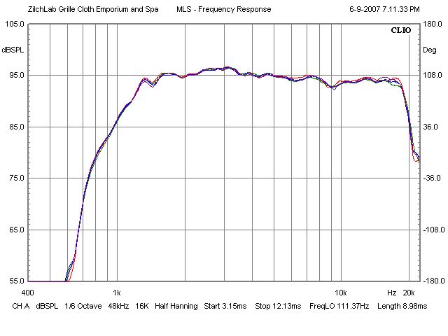
Here's Brandon's measurements of BMS 4540:
http://sites.google.com/site/drivervault/driver-measurements/acoustic-elegance-td12m/bms-4540nd
Also on the Pyle waveguide:
http://sites.google.com/site/driver...-knock-off/frequency-response-with-bms-4540nd
These were running on Altec Model 19 crossovers, of all things, 1.2 kHz.... 😀
Here's Brandon's measurements of BMS 4540:
http://sites.google.com/site/drivervault/driver-measurements/acoustic-elegance-td12m/bms-4540nd
Also on the Pyle waveguide:
http://sites.google.com/site/driver...-knock-off/frequency-response-with-bms-4540nd
Last edited:
Appart from high frequency directivity this type of driver also has a low mass corner.
In a c.d. device this is the frequency where on axis roll off begins, and in this driver this may well be as low or lower than 1kHz.
If you then want a flat on axis responce out to 16kHz. you need 24db. of boost, this neglecting other causes of roll off.
The SEAS T29 driver has a mass corner twice as high or more and is 6db. more sensitive and with a 25mm. dome has far better high frequency directivity.
It has a rated 1.4mm. pk.pk. excursion.
If you just do a few simple calculations you will find that the SEAS wins hands down.
rcw
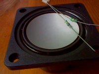
Oh, that looks very interesting. Is it possible to measure the diameter and depth of the diaphragm?Dont forget the possible lower xo point of a pro driver
A hifi dome wont go that low
To me thats the main reason
Others may favour the higher sensitivity
The cheap waveguides I have bought needs to have the 1.3/4 thread insert cut off, to modify it with mounting plate for the 1.5" BMS Im looking at
Btw, around here the BMS is priced exactly like the 1" B&C
Many other drivers are far to expencive
Anyway, when cutting off the thread insert, I can try and mount the 2"(TB) inverted alu cone tweeter I bought recently
THAT could be crossed very low
Also planning to buy a cheap 10" to mount in my old Lowther Acousta horns
Will be interesting to see how it works
Very interesting to look at the IR and CSD of compression drivers.🙂Here are four BMS 4555s on JBL PT-F95HF. They'll mate with any of the half-dozen available variants of that 1.5" throat waveguide family. You do have to drill mounting holes in the flanges:
These were running on Altec Model 19 crossovers, of all things, 1.2 kHz.... 😀
Here's Brandon's measurements of BMS 4540:
http://sites.google.com/site/drivervault/driver-measurements/acoustic-elegance-td12m/bms-4540nd
Also on the Pyle waveguide:
http://sites.google.com/site/driver...-knock-off/frequency-response-with-bms-4540nd
Wish he had CSD for the Geddes wave guide.
I already KNOW what causes the dip and I've posted it here a number of times. Its the mouth diffraction which adds out of phase from the direct sound at precisely one frequency when precisely on axis. An elliptical mouth will make this go away.
We've been all through this before, where have you been?
Me, not here.
I have measured the quantity of acoustic energy which come back to the compression with 3 shapes of end tube:

An externally hosted image should be here but it was not working when we last tested it.
I notice 2 things, the very good linearity of single tube and the very effective elliptic shape for the reflection (better than horn above 4Khz).
However, the directivity of elliptic shape is very special.
Wish he had CSD for the Geddes wave guide.
It's in the Horn vs. Waveguide thread, early pages, derived from his measurements....

Most probably you are referring to my work based on Ears measurements shown in the "Beyond.." thread at:
(could you please point us to the other place if not the case?)
http://www.diyaudio.com/forums/showthread.php?p=1821292
Courtesy Earl
OS wave guide at 0 deg:

OS wave guide at 15 deg:

OS wave guide at 30 deg:

OS wave guide at 45 deg:

48kHz Files provided by Earl I converted in CoolEdit and processed by ARTA to get CSD.
Looks pretty much excellent for me with respect to decay time
🙂
Michael
I haven't seen this to be done elsewhere – sadly very few measurements of Earls original OS wave guide available.
But it wasn't measured using SoundEasy, so I really can't compare the data.
What's the difference with CSD from ARTA versus SoundEasy ?
Michael
Last edited:
Earl - whats been exactly the wave guide's included angle (and round ouver radius at mouth) of the above measurements?
I'd like to run a simu with that values to compare with your measurements.
Michael
I'd like to run a simu with that values to compare with your measurements.
Michael
Last edited:
CD horn is quite real based on simulation for axisymmetric condition. It just doesn't get there with a 90deg wall angles. Additionally, these also become quite sensitive to revealing other problems that may be misinterpreted as caused by the horn/guide.
From where I sit thats not true.
I think soongsc refers to constant directivity *plus* Gaussian beam behaviour – meaning that there are no swiss cheese holes in the sound field - especially on axis, to be more specific – like showing up below in the 4-5kHz region .
http://www.diyaudio.com/forums/showthread.php?p=1924924

OS of 90 deg included angle with a 100mm / 4" round over to infinite baffles:
or also seen in Soongsc' simus at the very top end
http://www.diyaudio.com/forums/showthread.php?p=1916139
Michael
Last edited:
1. SoundEasy compares against a reference impulse. I don't know how whether the ARTA data considers this or not, therefore we cannot compare.
...
What's the difference with CSD from ARTA versus SoundEasy ?
Michael
2. The resolution of the original data is unkown. It seems like the resolution is low such that we cannot view with full time scale of 1ms without running into resolution problems.
3. It seems to me that most CSD data just steps through the time range from the beginning, while SE seems to generate the second line after the impulse first returns to null. This allows better visualization of the residual part of the decay. So it's hard to compare with other software CSD.
- Home
- Loudspeakers
- Multi-Way
- Geddes on Waveguides