metalman said:Marc,
This is the change I mentioned. The values I provided for you will work, but the ZTX450 is running close to it's 1W maximum rating. The part number of this figure may be off from my previous schematics (I did a quick copy from a spice model I use), but it is a pretty simple change so I don't think this will cause too much confusion.
Cheers, Terry
Ok i will add the 500R between neg rail et the CSS
Marc
XGC SuSy - Integrated - DRV134
Hi guys,
after reading the whole thread, your work and effort inspired me to build again an amplifier after 15 years living without soldering iron (changed line of ocupation from analogue electronics to software).
The thing is, metalman (all hail !) is making XGC SuSy (or BIG SuSy - nice name for an amp - Balanced Input Gainclone) better and better, but as it usually happens, better circuit tends to develop complexity, which is contrary to the philosophy of GC.
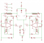
You guys noted the diff. drivers (OPA1632, DRV134 ...) and i think they are natural choice for the job of the input stage. If you look at the internal schematic of DRV134 (left side of the attached drawing) you can see what I mean (it has input buffer and diff. amp.). On the right side is the proposal for integrated amp as I intend to build it (or maybe with LM3886 in inverted mode - it has some clear advantages). Please, note that pins 7/1 and 8/2 are not short cuicuited but used for SuSy feedback.
I don't have internal schematic for OPA1632 but I supose it can't be much different (since it's differential 😉 ). On paper it beats DRV134 hands down, but it seems to lack pins for SuSy feedback (7 and 2 at DRV134).
Mr. Pass, veteran, 00940 (metalman is so happy with his ZTXs 😉 ) and the rest of you guys, please let me know what you think.
Thanks !
Hi guys,
after reading the whole thread, your work and effort inspired me to build again an amplifier after 15 years living without soldering iron (changed line of ocupation from analogue electronics to software).
The thing is, metalman (all hail !) is making XGC SuSy (or BIG SuSy - nice name for an amp - Balanced Input Gainclone) better and better, but as it usually happens, better circuit tends to develop complexity, which is contrary to the philosophy of GC.
You guys noted the diff. drivers (OPA1632, DRV134 ...) and i think they are natural choice for the job of the input stage. If you look at the internal schematic of DRV134 (left side of the attached drawing) you can see what I mean (it has input buffer and diff. amp.). On the right side is the proposal for integrated amp as I intend to build it (or maybe with LM3886 in inverted mode - it has some clear advantages). Please, note that pins 7/1 and 8/2 are not short cuicuited but used for SuSy feedback.
I don't have internal schematic for OPA1632 but I supose it can't be much different (since it's differential 😉 ). On paper it beats DRV134 hands down, but it seems to lack pins for SuSy feedback (7 and 2 at DRV134).
Mr. Pass, veteran, 00940 (metalman is so happy with his ZTXs 😉 ) and the rest of you guys, please let me know what you think.
Thanks !

Re: XGC SuSy - Integrated - DRV134
How bad could it be?
😎
juma said:please let me know what you think.
How bad could it be?
😎
Re: XGC SuSy - Integrated - DRV134
HI Juma,
I like it a lot. 🙂
I am working on a schematic, I will post more later.
juma said:Here is the drawing
HI Juma,
I like it a lot. 🙂
I am working on a schematic, I will post more later.
Re: XGC SuSy - Integrated - DRV134
The DRV134 is a typical balanced driver. It just integrates 3 opamps and a few resistors. The opa1632 is one single fully differential opamp. Balanced inputs, balanced outputs.
2/ The OPA1632 has no pins for feedback because it doesn't need them. It is not a single ended to balanced converter. The schematic of the ths4130 is quite clear. You integrate the power opamps inside the feedback loop of the opa1632. The resistors of the feedback loop are external, not internal.
1/ The OPA1632 is /very/ different from the DRV134. The internal schematic can be found in the datasheet of the THS4130 (it's so similar in specs many wondered if the opa1632 wasn't simply a rebadged ths4130). see http://focus.ti.com/lit/ds/symlink/ths4130.pdf , p. 14juma said:I don't have internal schematic for OPA1632 but I supose it can't be much different (since it's differential 😉 ). On paper it beats DRV134 hands down, but it seems to lack pins for SuSy feedback (7 and 2 at DRV134).
The DRV134 is a typical balanced driver. It just integrates 3 opamps and a few resistors. The opa1632 is one single fully differential opamp. Balanced inputs, balanced outputs.
2/ The OPA1632 has no pins for feedback because it doesn't need them. It is not a single ended to balanced converter. The schematic of the ths4130 is quite clear. You integrate the power opamps inside the feedback loop of the opa1632. The resistors of the feedback loop are external, not internal.
XGC SuSy - Integrated - DRV134
Thanks for the data Ben !
As things stand now, OPA1632 would be a great choice for a bridged amp (since it is obvious from datashet that it can accept single ended input and turn it into balanced) so both power amp parts of the bridge can run in the same mode (INV or NON-INV), but here we want SuSy,
right?
And my idea was to simplify the whole deal : CD player -> Integrated amp -> Speakers (the keyword of GC deal is simplification). So, if we want to use OPA1632 for integrated version of SuSy amp we have to create balanced signal before it (I don't know if there are CD players with balanced output). That implies use of one more OPA1632 in single-ended input mode, and that's two OPA1632 chips per channel. I have doubts that this configuration will perform better against only one DRV134 per channel (as Mr. Pass said: "how bad could it be?")
What do you people think?
Re: XGC SuSy - Integrated - DRV134
To be honnest, I still don't quite understand how you get a X-amp with the drv134 while with the opa1632 it is obvious (I'm no EE). I guess I need to study your schematic a bit more I guess.
Wrt to balanced source. Yes, with one opa1632, we basically have the very same thing as the xgc with the 2 transistors. So a balanced source or converter would be better ahead.
juma said: Here is the drawing
In the right schematic, I think the +out and -out labels on
the outputs of the lm3886 need to be swapped, since the lm3886's
are run in non-inverting mode and pin 8 on drv 134 is positive out.
Then also the feedback to pins 2 and 7 need to be swapped.
Tom
Re: Re: XGC SuSy - Integrated - DRV134
LM3886 is placed inside counter-phase feedback loop of OP-AMP inside DRV134. Same thing happens with transistors in Mr. Nelson's/metalman's schematic.
Wright you are Tom. Sharp eyes , thank you (my bad)
So far I have only all the chips and toroid (600 VA, 4 x 20V AC) and I'll be hunting for the rest of the parts in next couple of weeks (that's not an easy task in Greece ). When this thing materialize we'll judge it further.
Thanks, guys
(corrected drawing )
00940 said:To be honnest, I still don't quite understand how you get a X-amp with the drv134
LM3886 is placed inside counter-phase feedback loop of OP-AMP inside DRV134. Same thing happens with transistors in Mr. Nelson's/metalman's schematic.
Tom2 said:
In the right schematic, I think the +out and -out labels on
the outputs of the lm3886 need to be swapped.
Then also the feedback to pins 2 and 7 need to be swapped.
Tom
Wright you are Tom. Sharp eyes
, thank you (my bad) So far I have only all the chips and toroid (600 VA, 4 x 20V AC) and I'll be hunting for the rest of the parts in next couple of weeks (that's not an easy task in Greece
). When this thing materialize we'll judge it further.Thanks, guys
(corrected drawing )
Attachments
After all is said and done ...
Well, after some building and testing, here are my conclusions :
1. DRV134 is not the right thing for SuSy - error current which flows through emitors of diff. pair can not be achieved this way (op-amps in DRV134 are not current-feed type, neither their configuration inside IC is appropriate).
2. OPA1632, being a true diff. amp is the thing, but without source with balanced output there has to be one more stage to convert unbal. signal to balanced, which further complicates the whole deal and the benefits become questionable, because :
3. The SuSy is basically a bridge-configured amp. Using only 2 of LM3886 per channel we get into predicament with output impedance. With 8 Ohms speakers every side of the bridge sees 4 Ohms, and when speakers impedance drops below 8 Ohms 3886s are under a lot of strain and their performance deteriorates. I have the 4 Ohm speakers which I like very much and wouldn't exchange, and therefore am not the one who can apply this solution. Of course this can be helped by paralleling 3886s and using 4 of them per channel, but that's a PA amp, not a home Hi-Fi (IMHO).
4. Basically, metalman's schematic is OK if you have speakers with steady impedance and don't mind coupling capacitors on transistors' colectors. In fact, these caps are thorn in my eye. What you gain through SuSy effect, you lose on them. What is needed is direct coupling (using OPA1632, not transistors) and that can be achieved by some adjusting of IC's offset voltage.
Although tempting, this concept is not my cup of tea right now, and I'll be going for something more simple.
Cheers all !
Well, after some building and testing, here are my conclusions :
1. DRV134 is not the right thing for SuSy - error current which flows through emitors of diff. pair can not be achieved this way (op-amps in DRV134 are not current-feed type, neither their configuration inside IC is appropriate).
2. OPA1632, being a true diff. amp is the thing, but without source with balanced output there has to be one more stage to convert unbal. signal to balanced, which further complicates the whole deal and the benefits become questionable, because :
3. The SuSy is basically a bridge-configured amp. Using only 2 of LM3886 per channel we get into predicament with output impedance. With 8 Ohms speakers every side of the bridge sees 4 Ohms, and when speakers impedance drops below 8 Ohms 3886s are under a lot of strain and their performance deteriorates. I have the 4 Ohm speakers which I like very much and wouldn't exchange, and therefore am not the one who can apply this solution. Of course this can be helped by paralleling 3886s and using 4 of them per channel, but that's a PA amp, not a home Hi-Fi (IMHO).
4. Basically, metalman's schematic is OK if you have speakers with steady impedance and don't mind coupling capacitors on transistors' colectors. In fact, these caps are thorn in my eye. What you gain through SuSy effect, you lose on them. What is needed is direct coupling (using OPA1632, not transistors) and that can be achieved by some adjusting of IC's offset voltage.
Although tempting, this concept is not my cup of tea
right now, and I'll be going for something more simple.Cheers all !
Working on SuSy layout(s) need some input
Ok folks,
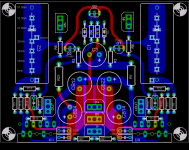
I have promised a few people to get this done, and finally I have some time to make it happen. Here is my first layout for SuSy. It is indeed similar to what Kari did, but with my own "twists". I like the symmetry of the layout very much, but it requires that the LM3886s be mounted one on top, and one on the botton, not exactly simple, and many probbaly will not like that.
For reference here is that image:
Ok folks,
I have promised a few people to get this done, and finally I have some time to make it happen. Here is my first layout for SuSy. It is indeed similar to what Kari did, but with my own "twists". I like the symmetry of the layout very much, but it requires that the LM3886s be mounted one on top, and one on the botton, not exactly simple, and many probbaly will not like that.
For reference here is that image:
Attachments
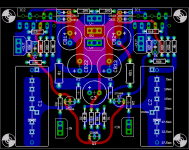
Now, that layout has a lot going for it, but the convenience factor is low (HS mounting will be tricky).
So I did this layout as well, which is a lot the same, but has the LM3886 on the same side. I had to compromise just a tad to make it work, but I think it still is a solid layout.
What do you folks think? Is the pain in the rear for mounting worth the "symmetry" of that layout? Or is this just as good or better because it is more accessible and easier to build?
Attachments
FWIW, I am getting ready to order some boards I have put together to try some stuff out. LM3886 and LM4780 boards are single chip stand-alone capable. I have a single board that forms the core of the SUSY that can be connected to the amp boards. So I should be able to test both single 3886 on each side as well as 4780 paralleled (i.e. bridged, and bridged-parallel).
Of course, if the basic amp boards don't work right I won't get so far as testing the rest. 🙂
My main speakers hit 2.8ohm though, so to use this amp configuration with them I will either have to drop to 20-22V rails and the 3886 or work with the BPA configuration.
I'll also need a new pre, but I've decided it's not worth working up yet another PCB and will probably snag the kit Russ is offering. Still not sure what to use for volume control on that.
C
Russ,
I recently prototyped the circuit with the values I provide you for the Twisted version, and I found one minor correction is required. The circuit as it exists now will work fine with any preamp that has its output correctly ground referenced (i.e. the Twsited BoSoZ will work with it just fine).
However, with the increased bias of the input differential pair, the ZTX450's draw a small (~80uA) current from the collector that pulls down the inputs to about -7V reference to ground. As soon as it is connected to a preamp with ground referenced outputs the problem goes away.
In the interest of correctness, two new resistors should be added to the circuit to ground reference the inputs. Value should be 20-25kohm and connect each input to ground. That fixes it perfectly.
Hope this doesn't throw a wrench into your work.
Terry
metalman said:In the interest of correctness, two new resistors should be added to the circuit to ground reference the inputs. Value should be 20-25kohm and connect each input to ground. That fixes it perfectly.
Hope this doesn't throw a wrench into your work.
Terry
Great input Terry!!! I have made the change, it was no problem. I also added a connector for IN GND, had neglected it earlier.
Thanks so much!

20-25k input to ground? I can do that, but will have to rework my bridge board now. 😛 Ahh well. At least this can be wired in easily enough - I have boards and components to test this with both a single 3886 per side and a single 4780 per side somewhere in the process of being made or being shipped to me. Should be interesting. The good news is they're modular enough that the actual chip boards can be used alone, and the bridge network should be usable with other boards - possibly, for example, with Mauro's concept (though that may require component value tweaking - I don't know).
I'll post up some pics as things progress. Hopefully y'all don't get to laugh and point at burn marks. 😉
Russ, If you have any vague interest in any of the stuff I've been working on, let me know. I've already placed my order for the X-BOSOZ and a Joshua Tree from you.
C
- Home
- Amplifiers
- Pass Labs
- GC SuperSymmetry