Hi,
Since for any differential amplifier to work properly to cancel out noise, matching of components is critically important. For my case, the output offset voltage for both channels of LM4766 varies quite a lot. Will this cause the "X" circuit not to work in its optimum state? Is there any way to put a VR for adjustment of offset voltage so that it works symmetrically?
Hi Metalman,
I'll implement DRV134 first. But not sure if this is enough as a driver or should I add another OPA2134 unity buffer after DRV134. What do you think?
Thanks.
Re:still sharp
but that would give a flatter curve?
next thing I wanted to try was .1µ / 1ohm...
what's the effect of using wirewound resistors? problem with high frequencies?
m.
jh6you said:
What about 10ohms 0.47uF? I would recommend to try.
but that would give a flatter curve?
next thing I wanted to try was .1µ / 1ohm...
what's the effect of using wirewound resistors? problem with high frequencies?
m.
There must be certain formation of frequency bandwidth curves. I however have no idea about the curves. I have just tried different Zobel values with my Monolithic SuperSymmetry (MSS) amp, after all for my listening taste. At the moment, I have + speaker terminal/10 ohms/0.47uF/10 ohms/- speaker terminal, where “/” means soldered point.
Now I am building three MSS amps, for my near future plan of home theater. After finishing this, I might consider to build one GC SuperSymmetry and compare the sound with MSS.
Good luck to you 🙂
-------------------
Wire-wound R fine for me.
Now I am building three MSS amps, for my near future plan of home theater. After finishing this, I might consider to build one GC SuperSymmetry and compare the sound with MSS.
Good luck to you 🙂
-------------------
Wire-wound R fine for me.
loong,
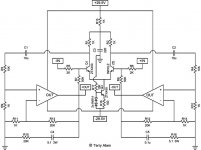
I have attached to this post the schematic of the amp as it exists today. I have not included the powersupply details in it though. The PS I am using is more or less Pedja Rogics regulated supply, and the exact voltage for the rails is not critical.
Ipanema,
I had a look at the datasheet for teh DRV134, and it says that it can output 7Vrms into a 600ohm load, which I believe provide adequate drive for the Susy GC inputs.
jh6you,
My zobel setup is in my schematic attached to this post, or per your terminology, I am using +spkr/0.1uF/5.1R/GND/5.1R/0.1uF/-spkr, which is what Nelson suggested.
diering,
My comment about the wirewound zobel resistor was meant to indicate that I used the cheapest 3W 5.1R resistors I could get my hands on, and didn't bother with anything exotic. One thing my choice does add to the puzzle is that these resistors do not have a particularly low inductance, but I don't really think that it makes a real difference here.
I gave your brightness issue a fair bit of thought last night, and I have some ideas. A key point is that, due to the extremely high open loop gain of the chips, this amp (using the values I have identified so far) has a narrow stability margin and thus the more feedback signal required the more likely it is to start oscillating, which could be the cause of your brightness. In my amp, C1 and C2 are 10uF polypropylene film caps. Looking at the pictures from your earlier setup, it looks like you are using electrolytic caps for C1 and C2, which will add more local distortion at high frequencies than film caps, requiring an increased feedback level at high frequencies that could initiate oscillatinions. I do not know this for certain, but it seems a likely possibility. If my assumption is correct, then there are two solutions to pursue:
1) Replace your 10uF electrolytics with film caps to reduce the capacitor distortion at high frequencies.
2) Reduce the values for R9 and R10 to increase the stability margin of the amp. (I have been thinking about trying this in an attempt to improve the amp's performance when driven single-ended). Give these a try and see how it turns out.
Cheers, Terry
Attachments
I am using wire wound resistors too, that's why I wondered if they could be a problem...
No I don't want to use film caps: too big, too expensive 🙁
Yes I thought too there might be too much gain - so neg-feedback could be higher, too? Don't the two feedbacks have to be matched somehow?
So yours is not too bright, say compared to your rotel amp?
No I don't want to use film caps: too big, too expensive 🙁
Yes I thought too there might be too much gain - so neg-feedback could be higher, too? Don't the two feedbacks have to be matched somehow?
So yours is not too bright, say compared to your rotel amp?
dieringe said:I am using wire wound resistors too, that's why I wondered if they could be a problem...
Not likely. The resistance they represent is the key to damping
out the performance. It would take a lot of inductance to
create trouble.
Originally posted by dieringe
So neg-feedback could be higher, too? Don't the two feedbacks have to be matched somehow?
Actually, if I understand it correctly, the problem is that there is too much feedback (well, actually that the feedback level is so high that it is arriving slightly out-of-phase with the input signal)! That is why we throw away the extra gain via the voltage dividers of R3/R9, and R4/R10, so the chips can produce same level of gain with a smaller feedback signal.
If you look at my evolution of the circuit, you will see that I originally set the closed loop gain to a little under 30dB, and eventually increased it to 32dB by reducing the level of feedback via the supersymmetric loop (increasing R7, R8). At the same time, I went from throwing away 0.1dB at the voltage dividers to throwing out 21dB (increased R3 & R4, decreasing R9 & R10). In doing this, I reduced the amount of feedback in the whole circuit by 23dB.
Let me know if this explanation makes sense to you. If not I will try to make it clearer.
My amp right now is very listenable. Yes, it is on the bright side of the spectrum, but it comes across more as detailed rather than harsh. In fact my wife has actually used the word "smooth" to describe it, which I completely accredit to the effects of supersymmetry. I prefer it to my Rotel in all aspects. Too bad we're separated by an ocean and a continent, or I'd invite you over to have a listen and have a laugh at the chassis-less spaghetti-mess of point-to-point wiring that is my amp. One of these days one of my cats is going to accidentally get electrocuted, especially now that I am listening to it a lot.
One last suggestion is that I noticed your PS decoupling capacitance is a wires length away from your chips, whereas I have 1500uF caps soldered directly to the chip pins. I don't suspect that this is your problem, as according to the chipamp guys this causes fuzziness not brightness, but it was the only other significant difference I could see from the pictures.
Terry
driving a susy
you could also make a really simple single to balanced converter with (as we're using them anyway) a good quality, high output opamp. schema attached (could it be easier?).
You can even use some of the more exotic line-drivers (high output current) like the ad826 or the ad8620 which, the data sheet states, is useful in 'high performance audio' applications.
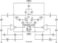
btw terry, the labels on the left zobel are incorrect 😉
you could also make a really simple single to balanced converter with (as we're using them anyway) a good quality, high output opamp. schema attached (could it be easier?).
You can even use some of the more exotic line-drivers (high output current) like the ad826 or the ad8620 which, the data sheet states, is useful in 'high performance audio' applications.
btw terry, the labels on the left zobel are incorrect 😉
Attachments

metalman said:..., which is what Nelson suggested.
Understood that C4-5 and R15-16 are suggested by Nelson Pass.
Nevertheless, the values, we could choose properly on our own. I tried several different values, e.g. 0.1uF, 0.2uF, 0.3uF, 0.4uF, 0.5uF, ... by paralleling them, using very cheap Panasonic film caps of 0.1uF. Cost was little.
DOH!!!!!!Originally posted by Matjans
btw terry, the labels on the left zobel are incorrect
The labels on the right side are correct, but the left is FUBAR (lousy duplicate command gets me every time). Unfortunately the schematic is on my computer at work, so I can't correct it util tomorrow. Thanks for the keen eye, and I'll post the corrected version tomorrow.
You are absolutely correct! I was mainly trying to indicate that I personally didn't have any special reason beyond using Nelson's suggestion as a starting point, which happens to work reasonably well in my setup. I definitely haven't spent any time yet trying to optimize the zobel values, and there is probably room for improvement. By the way, I have been meaning to compliment you for your great work on the MSS. If you ever find your way around to building a Susy GC, I will be very interested to hear your opinions on the comparison.Originally posted by jh6you
Understood that C4-5 and R15-16 are suggested by Nelson Pass.
Nevertheless, the values, we could choose properly on our own.
For those who don't already know, you can calculate the zobel transition frequency by:
freq = 1/(2*pi*R*C)
Cheers, Terry
Thanks for nice wording... shyly...
After completion of the new MSSs, I will try to replace the inside of the old MSS with GCSS.
Cheers
After completion of the new MSSs, I will try to replace the inside of the old MSS with GCSS.
Cheers
I doubt that this simple calculation is right, doesn't it depend on the speaker impedance? Impedance of capacitor is 1/(2pi f C) which adds to the resistor, the two parallel to speaker to eat up the high frequencies...
BC547
I use BC547 for diffpair and CCS. That's what I have lying around in masses.
They can't be that bad, can they?
I use BC547 for diffpair and CCS. That's what I have lying around in masses.
They can't be that bad, can they?
I doubt that this simple calculation is right, doesn't it depend on the speaker impedance?
The calculation Terry provided gives the cut-off frequency (freq. where equal volatge is dropped across both R and C) of the Zobel.
I'm not really sure, but it seems reasonable that the 'text book ideal' Zobel would maintain unity power factor (or at least a constant system Z) through out the frequency range of the amplifier. Because we are DIYers, instead of using a one size fits all Zobel like a manufacturer would use, perhaps the Zobel values could be optimized for a specific speaker.
Originally posted by dieringe
I doubt that this simple calculation is right, doesn't it depend on the speaker impedance? Impedance of capacitor is 1/(2pi f C) which adds to the resistor, the two parallel to speaker to eat up the high frequencies...
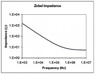
Let me show a couple of graphs. The first one below shows the series impedance of my Zobel values (0.1uF and 5.1ohm) as a function of frequency.
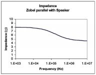
The second graph shows the impedance the amplifier will see at its output due to the parallel impedance of an ideal speaker (8ohm across the entire freq. range) and the zobel.
Attachments
If that can be achieved, that is the ideal approach. The problem in practice is that you now need detailed infomation about the speaker crossover and drivers behaviours. Also, I must admit that doing so is probably a little beyond me at this stage (or at least would take a lot of thought, effort and time to do so).Originally posted by Gaucho
Because we are DIYers, instead of using a one size fits all Zobel like a manufacturer would use, perhaps the Zobel values could be optimized for a specific speaker.
Early a similar question was asked of Nelson, and he replied that any generic bipolar transistor should be suitable. I doubt they are a problem.Originally posted by Diering
I use BC547 for diffpair and CCS. That's what I have lying around in masses. They can't be that bad, can they?
If that can be achieved, that is the ideal approach. The problem in practice is that you now need detailed infomation about the speaker crossover and drivers behaviours. Also, I must admit that doing so is probably a little beyond me at this stage (or at least would take a lot of thought, effort and time to do so).
I guess this is where the Fostex/Lowther guys catch a break.🙂
With a single driver, you can put a non-inductive resistor in series with the speaker and monitor the voltage drops across the driver (or perhaps driver and cable combined) and the resistor through a frequency sweep. Once you have your impedance curve you can calculate the Zobel values, fooling your amp (assuming we ignore any resonant peaks) into thinking it's driving pure resistance. That being said, I think the same approach could be used to some effectiveness in a multi-driver system.
- Home
- Amplifiers
- Pass Labs
- GC SuperSymmetry