Member
Joined 2002
jleaman said:Id like to get a group buy on board's Any one else think the same thing ?
Ofcourse!! Digi01 was going to make PCBs very similar to these and there was quite an interest in those so I think there will be quite an interest in this 😉
Member
Joined 2002
PMA said:I do not like stupid argueing.
http://www.elecdesign.com/Articles/ArticleID/1478/1478.html
Me neither.
I know that article, and I have this same table on a doc somewhere:
http://www.elecdesign.com/Files/29/1478/Figure_06.gif
Curious...
Everytime there's only a small bypass cap near the PSU pins what suffers is the bass.
Any experient listener will know that when the bass is not tight, the midband and treble precision and detail vanishes.
On the OPA627 datasheet, page 9:
"Power supply connections should be bypassed with good high frequency capacitors positioned close to the op amp pins. In most cases 0.1mF ceramic capacitors are adequate.
The OPA627/637 is capable of high output current (in
excess of 45mA). Applications with low impedance loads or capacitive loads with fast transient signals demand large currents from the power supplies. Larger bypass capacitors such as 1mF solid tantalum capacitors may improve dynamic performance in these applications."
Notice: every cable is by itself a capacitive load.
Fast transient signals = music.
I'm sorry I have to "translate" this...
LM6172 datasheet, page 16:
"Bypassing the power supply is necessary to maintain low power supply impedance across frequency. Both positive and negative power supplies should be bypassed individually by placing 0.01 μF ceramic capacitors directly to power supply pins and 2.2 μF tantalum capacitors close to the power supply pins."
These guys insist in tantalum caps, I don't like them...
No matter what you guys say, I do always think in AUDIO, while your approaches are generic from datasheets, docs, fancy papers.
If stability is the explanation for everything, how come two different op-amps sound different, even if correctly used?
Stability is the minimum design requirement, it is mandatory.
Audio is a totally different league, another story, much more demanding.😉
Carlos,
I think I asked before, but what do you consider small? I've seen plent of designs that do 10uF-47uF + 0.1uF by the opamps...
Mike
I think I asked before, but what do you consider small? I've seen plent of designs that do 10uF-47uF + 0.1uF by the opamps...
Mike
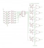
Here is an input selector based on the 74c373 Octal latch chip. i thought it might be handy to go with this for someone.
you can have as many as 8 input pairs. i will probably use 4 but design the board for up to 6. that is because for 8 you would need another hex buffer chip and i think it is unlikely anyone would need that many inputs.
momentary switches are buffered to help protect CMOS from static.
you could probably get away without using the buffers, and just bring the pins on the 373 up instead but buffer chip is very cheap.
the diodes from the buffers to the ENC input ensure that only one output is high at a time. just any small signal diode.
relays and LEDs are driven by cheapo 2n2222 NPN transistor or similar.
the LEDs would be next to the corresponding momentary switch.
This will be 2 boards. 1 will be at the front of the preamp and have the buttons, chips, and drivers.
the other will be just the relays and be at the back of the preamp.
Attachments
neutron7 said:Here is an input selector based on the 74c373 Octal latch chip. i thought it might be handy to go with this for someone.
you can have as many as 8 input pairs. i will probably use 4 but design the board for up to 6
momentary switches are buffered to help protect CMOS from static.
you could probably get away without using the buffers, and just bring the pins on the 373 up instead but buffer chip is very cheap.
the diodes from the buffers to the ENC input ensure that only one output is high at a time. just any small signal diode.
relays and LEDs are driven by cheapo 2n2222 NPN transistor or similar.
the LEDs would be next to the corresponding momentary switch.
This will be 2 boards. 1 will be at the front of the preamp and have the buttons, chips, and drivers.
the other will be just the relays and be at the back of the preamp.
Excellent, thank you!
Will your design be single layer?
How hard is it to have a rotary encoder as a selection device?
that circuit would be different for a rotary encoder. you could use some kind of counter chip and then decode the outputs. i dont think a rotary encoder would be suitable for input selection though. they are too easy to turn and there is no "click" to tell you where you are.
i will try and make the board single sided, it should be fairly easy because no audio passes through any of the controller board, and there is no high frequency clocked logic to isolate.
i will try and make the board single sided, it should be fairly easy because no audio passes through any of the controller board, and there is no high frequency clocked logic to isolate.
neutron7 said:they are too easy to turn and there is no "click" to tell you where you are.
True but I always thought push buttons seem kinda cheap but it doesn't matter anyway, it sounds like a great design/plan!
neutron7 said:i will try and make the board single sided, it should be fairly easy because no audio passes through any of the controller board, and there is no high frequency clocked logic to isolate.
I ask because this imagine would be very popular if you could etch it yourself 😉
push buttons can be VERY nice if you (for example) use some metal rods and have them through holes in your front panel and they push the actual buttons on the other side. you can add springs to change how they feel.
Sure, thats what we all are waiting for,Id like to get a group buy on board's Any one else think the same thing ?
in tense excitement😀 😀 If I may feel free to suggest it, why not take this thing all the way, while you are at it! I mean a pcb kit with the PMA buffer, powersupply, and Neutron7's relay board.
And maybe soething else?
That could end up as a very fine preamp😉
Steen.
Carlos,
according to my experience, that is of course not as high and sophisticated as yours, the quality of bass depends only and only on preamp output stage design. Simple opamp will never make it. The best result is obtained with the lowest output impedance (5 Ohm) and highest output current capability (hundreds of miliamperes). No large cap bypassing on OPA627 compares to the high current output stage (0.5A) with 5 Ohm output impedeance.
Regards,
Pavel
neutron7 said:Here is an input selector based on the 74c373 Octal latch chip. i thought it might be handy to go with this for someone.
you can have as many as 8 input pairs.
That looks great Neutron, can't wait to see the PCB.
I'm also with Steeno on the "Preamp Kit" idea. I think the main issue with the kit is the PSU design, seems everyone has their own preference. I'm pretty happy with the simple regulated supply that I made, but I think it could be made better. I had the idea of using burried zener precision voltage references as regulators, with a transistor to increase the current capability. I'm not sure it would deliver enough current but should be very quiet.
PMA said:Carlos,
according to my experience, that is of course not as high and sophisticated as yours...
Regards,
Pavel
I'm sharing my experience.
We can discuss with an open-minded approach instead of taking all the threads into hillarious discussions.
PMA said:The best result is obtained with the lowest output impedance (5 Ohm) and highest output current capability (hundreds of miliamperes). No large cap bypassing on OPA627 compares to the high current output stage (0.5A) with 5 Ohm output impedeance.
Again, I was sharing my experience with the OPA627 (and some other op-amps) on how to get the best sound out of it.
Notice that on this circuit it is being used with the BUF634, which can deliver a max. current of ~250ma (TO220, heatsinked).
And yes, low output impedance is, also for me, a requirement.
As for the preamp, I use my own AD815 implementation, and very happy with it.😉
Du you have any theorectical explanation for your claims? Preamp with 500 mA outputPMA said:Carlos,
according to my experience, that is of course not as high and sophisticated as yours, the quality of bass depends only and only on preamp output stage design. Simple opamp will never make it. The best result is obtained with the lowest output impedance (5 Ohm) and highest output current capability (hundreds of miliamperes). No large cap bypassing on OPA627 compares to the high current output stage (0.5A) with 5 Ohm output impedeance.
 5 ohms out?
From what I have seen you have inserted resistors to increase the output impedance to 25 ohms, 50 ohms also?
Yes, thats the tough one. In post #95 I think, and onwards, we talked a bit on the subject. We better set up the demands for the psu🙂 (If we can cut through the noise that appears now and then on this thread😀 ) If for starters we assume the psu is strictly for the linestage, then the 317/337 regulator is probably ok. But if it have to be RIAA 'ready', I guess a discreet regulator would be nice? As far as the relay board goes, I have no clue. Personally, I think that Alcaids Zener/CCs regulator looks very promising. The regs, after the big caps could be doubled to have seperate feed's for right and leftI think the main issue with the kit is the PSU design
channel. There is a link to it in post #97.
Any thoughts?
Steen.🙂
jleaman:
http://www.ettnet.se/~tobias/diy/opabuf/pcb_top.jpg
maybe i'll put that el.cap that isn't as close to the pin as the other closer later 😉
http://www.ettnet.se/~tobias/diy/opabuf/pcb_top.jpg
maybe i'll put that el.cap that isn't as close to the pin as the other closer later 😉
peranders said:
Du you have any theorectical explanation for your claims? Preamp with 500 mA output
From what I have seen you have inserted resistors to increase the output impedance to 25 ohms, 50 ohms also?
I do not have an exact explanation, just the results of listenning tests and intuition.
Regarding 25 ohms etc., yes it was the case, but I have not been visiting the forum for some time and have not been sharing experience.
PMA said:I do not have an exact explanation, just the results of listenning tests and intuition.
You will have to explain this to Upupa.😀
Member
Joined 2002
tobias_svensk said:jleaman:
http://www.ettnet.se/~tobias/diy/opabuf/pcb_top.jpg
maybe i'll put that el.cap that isn't as close to the pin as the other closer later 😉
I think you should order some of those boards id buy 4 for sure. If you need help let's talk further.
An externally hosted image should be here but it was not working when we last tested it.
- Status
- Not open for further replies.
- Home
- Amplifiers
- Chip Amps
- GC Preamp Suggestions