Upupa Epops said:To maxw : Hum + buzz : Have you connected together both supply grounds ( amp and relay ) ?
Power Grounds? the relay module runs off one set of the secondaries from that transformer and my pre runs off both secondaries (+/-V) from that (same) transformer. But the relay module is effectivly a passive component like a pot so it has nothing but resistance in the signal path?
If I uderstand to you correctly, you have symetric rails for amp and from one rail are also loaded relays ?
Upupa Epops said:If I uderstand to you correctly, you have symetric rails for amp and from one rail are also loaded relays ?
I draw you a diagram to make it more clear 😉
Attachments
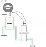
This is wrong and you hear buzzing. Ground of relay supply must be connected together with signal ground.
Upupa Epops said:This is wrong and you hear buzzing. Ground of relay supply must be connected together with signal ground.
I forgot to mention that both units have their own rectifiers.
In the relay unit the signal and the control circuits are completely separate, eg:
http://www.diyaudio.com/forums/showthread.php?postid=504649#post504649
??
Yes, I understand, but it is wrong. If you haven't connected it together ( both grounds ) buzz is coming to signal through capacity of coil vs. contact, 'cos supply for relay is floating ( not grounded ).
Gcollier, earlier in the thread you have a switch made from circuit boards and springs and stuff. why dont you just use some reed switches and a magnet on the shaft instead.
i just noticed you have a resistor instead of the 18p capacitor "c10" on the circuit you worked from.
error or a change you made?
error or a change you made?
neutron7 said:i just noticed you have a resistor instead of the 18p capacitor "c10" on the circuit you worked from.
error or a change you made?
Actually I did that intentionally, for many opamps that are unity gain stable you can use the 18p capacitor that Pavel suggests in his schematic, but most need nothing here. If you look at the buff634 datasheet you will see that in their headphone am circut (basically the same as this one) what recommendations they make for different opamps. My thought was to possibly use a resistor here to increase the gain of the OPA637 and leave the gain of the outer loop at unity. Not sure if it will help the stability of the OPA637 or not.
As for your idea to modify the switch I designed, could you post a rough sketch of what you are thinking.
G.
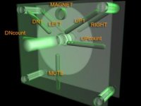
ok here is a sketch
its kind of hard to see but there is a disk with a magnet on it. when the magnet is close to the reed switches they turn on. they are those capsule shaped things.
I put up1 and upcounnt, you could have the fist switch nudge the volumel up or down 1 bit, and the next one start it counting up slowly.
you could do all sorts of things.
just an idea but you could make it so when you push on the knob there is a spring which brings the magnet closetr to another set of switches for controlling balance.
this is much less prone to dirt and so on than a contact on a spring.
you could put notches in the side of the disc for spring indents. i didnt put them in because i was having too much "fun" with the material editor trying to get the x-ray effect 🙂 and i ran out of time.
Attachments
neutron7 said:ok here is a sketch
its kind of hard to see but there is a disk with a magnet on it. when the magnet is close to the reed switches they turn on. they are those capsule shaped things.
I put up1 and upcounnt, you could have the fist switch nudge the volumel up or down 1 bit, and the next one start it counting up slowly.
you could do all sorts of things.
just an idea but you could make it so when you push on the knob there is a spring which brings the magnet closetr to another set of switches for controlling balance.
this is much less prone to dirt and so on than a contact on a spring.
you could put notches in the side of the disc for spring indents. i didnt put them in because i was having too much "fun" with the material editor trying to get the x-ray effect 🙂 and i ran out of time.
That looks pretty good. I think I get the basic concept, definately a more elegant approach than mine. Might cost a bit more, but as you said, dust would not really be an issue.
Nice job!
Member
Joined 2002

well its not bad but kind of litteral from the circuit
people may not want to have a shared ground or even a shered pair.
how about to be super versatile make a single channel the same size and shape as a brianGT board,
also besides the ground i would have from the main PSU CAPs a seperate trace to each chip then each one gets it own caps. thats just me though 🙂
n00beR said:Finally i have finished my own design and only one jumper w00t 😀.
I think every thing is present and correct, let me know what you guys think.
Thanks in advance
Craig.
neutron7 said:well its not bad but kind of litteral from the circuit
people may not want to have a shared ground or even a shered pair.
how about to be super versatile make a single channel the same size and shape as a brianGT board,
also besides the ground i would have from the main PSU CAPs a seperate trace to each chip then each one gets it own caps. thats just me though 🙂
Thats a nice layout, very compact, looks like it would be quite easy to divide the board down the center and have completely independant channels as Neutron suggests.
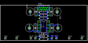
that looks nice n00b. what is that diode for? i dont remember seeing that in any versions of this circuit.
The diode is actually a CRD for biasing the opamp into class a. It ties the opamp output to -V.
I have been interested in headphone amplifiers for a while, and its one of the easier options for class a biasing. 😉
Its not as efficient as say a JFET cascode, but is more desirealble than a simple resistor. A CRD essentially a JFET and a resistor in a simple package.
I plan on doing some experiments with biasing in headphone amplifiers so I may integrate this into a preamp in the future.
Thanks for your comments, I will post my results soon.
Craig
I had some time this weekend to etche and populate a preamp board. I attached a photo, looks pretty nice IMO. I'm happy with the way everyting fit. I haven't tested it out yet, and I still need to attach the heatsinks to the BUF634's. Right now I have the gain set to about 8 as I am using OPA637 but I will lower it when I install some OPA627's. You may notice a few onpopulated holes in the boards, these are for some additional options such as an alternative input to bypass the DS1802, and a feedback resistor or capacitor on the OPA. I hope to audition it tonight but first I need to construct all the cables for the molex connectors. 😀
G.
G.
Attachments

And here is a shot of the PSU. Nothing Fancy, One pair of LM317/337 delivering +/- 15V for the OPA/BUF combo and another pair to deliver +/-2.5 V for the DS1802. The Big caps in the back are 12000uF Nichicons. I also decoupled the supply at the regulator supply pins with 10uf and 0.22 uF caps (not likely to do much but what the heck I had the space). The 15v output has a pair of 470uF caps and there is 220uf per rail on the 2.5V lines.
Turned out mighty nice I think...just forgot to drill the holes for the standoffs...oh well easy enough. 😉
G.
Turned out mighty nice I think...just forgot to drill the holes for the standoffs...oh well easy enough. 😉
G.
Attachments

- Status
- Not open for further replies.
- Home
- Amplifiers
- Chip Amps
- GC Preamp Suggestions