Gcollier said:Carlos...good advice is good advice. 😀 In your preamp design I believe you used ceramic caps for decoupling...did you try polypropylene, do you think it would make a difference?
As long as the caps are small, you can use polyprop.
Don't use big caps or the electrolythincs will be too far from the chip's pins.
Gcollier said:Also what are your thoughts on setting the gain of the internal loop high to keep the opa637 stable and reducing the gain of the outer loop?
What internal loop?😕
Maby I missed something here, but isn't this an op-amp+BUF634 on the feedback loop-based pre?
You only have one feedback loop.
... too far from chip pins ...
What is correct distance from chips pin, Carlos ? 😀 What is lengh of wave at 20 kHz ?
What is correct distance from chips pin, Carlos ? 😀 What is lengh of wave at 20 kHz ?
Re: ... too far from chip pins ...
If you only think 20Khz you are short sighted.
Maby you believe that everything above this doesn't matter.
Maby you think that everything above this can't interfere with the 20hz-20khz range.
I find this unbelievable.
I advise you to use a noisy PC switching PSU with your (non band-limited) amps.
Why bother?
It switches higher than 20khz.
But the noise will be as clear as the music, waaay down below.
Harmonics?
Whazzat?
Upupa Epops said:What is correct distance from chips pin, Carlos ? 😀 What is lengh of wave at 20 kHz ?
If you only think 20Khz you are short sighted.
Maby you believe that everything above this doesn't matter.
Maby you think that everything above this can't interfere with the 20hz-20khz range.
I find this unbelievable.
I advise you to use a noisy PC switching PSU with your (non band-limited) amps.
Why bother?
It switches higher than 20khz.
But the noise will be as clear as the music, waaay down below.
Harmonics?
Whazzat?
jleaman said:
There ya go : O ) I defiantly want a board : O )
J'
steenoe said:I'll second that. Looks really good🙂
Steen.
Well the one I etched last night is going to have to sit until I get some proper resistors to put in it, but of course I etched this before I made those last few revisions...so tomorrow I will etch the new ones. ...I'll post the eagle files tomorrow as well.
One suggestion: Would'nt it be nice with a set of pads for an input that goes directly to the line stage? Just in case someone would not want to use the DS1802. Could probably be put in somewhere after the DS1802.
The preamp would be more flexible to implement in that fasion.
Just a thought🙂
Steen.
The preamp would be more flexible to implement in that fasion.
Just a thought🙂
Steen.
You could solder the input wires to the output pads that are for the chip.
There is really no need fo extra pads, remember space is money😉
Its still early for me so if my explanation is not clear im sorry 🙂
There is really no need fo extra pads, remember space is money😉
Its still early for me so if my explanation is not clear im sorry 🙂
Ok for the rotary encoder types with digital volume control in two easy steps...
Take two, three, four or however many AD5220, take one cesi EBE rotary hall effect encoder.
The up/down output from the encoder will need to be inverted, and connected to pin 2 of the ad5220, the encoded output from pins 3,6 or 10 (on the encoder) needs to be taken to pin 1 of the ad5220, and pin 7 of the ad5220 needs to be grounded.
Pin 1 on the encoder is the power, pin 2 is ground (psu of 7V will be ok)
Pin 8 of the ad5220 is V+ (psu of 7V), pin 4 is ground.
Downside - this is a linear taper, not log. So, either use a law faking resistor (not too shabby, or complex), or, a variable gain buffer (i.e the wiper is in the feedback loop) trickier, but still do-able (rod elliot has an example on his site)...
To display the 'volume' setting how about an AD5220 output to an LM3915 with a 10 led 'indicator', or for the Final Retro look, use a moving iron meter....
Some thougts, and I may put a circuit/ board together....
Owen


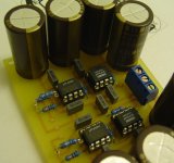
And testing it out......I tried using a 100k relay based pot but it's just too noisy, hummm and buzzz but maybe I am doing something wrong there.
But it goes fine with a 10k on the input. Less than 1mV offset 😀
I am using this PSU
Eagle files attached if anyone wants them 😉
But it goes fine with a 10k on the input. Less than 1mV offset 😀
I am using this PSU
An externally hosted image should be here but it was not working when we last tested it.
Eagle files attached if anyone wants them 😉
Attachments
Member
Joined 2002
I d like a psu board : O ) What's That nice Volume control board you have there on your link to the psu ?
maxw said:And testing it out......I tried using a 100k relay based pot but it's just too noisy, hummm and buzzz but maybe I am doing something wrong there.
But it goes fine with a 10k on the input. Less than 1mV offset 😀
I am using this PSU
That is a very nice design and layout. I see that you biased the OPA627 into class A with a diode...does the chip get hot? I'm not sure about the humm/buzz with the 100K pot, maybe switching out the 1M resistor on the input with something smaller would help? 😕
Gcollier said:
That is a very nice design and layout. I see that you biased the OPA627 into class A with a diode...does the chip get hot? I'm not sure about the humm/buzz with the 100K pot, maybe switching out the 1M resistor on the input with something smaller would help? 😕
I have a few opa627's biased into Class A on Pimeta & PPA boards ... No real additional heat that I've noticed. I'm not running them hot into Class A, only a few ma.
motherone said:I have a few opa627's biased into Class A on Pimeta & PPA boards ... No real additional heat that I've noticed. I'm not running them hot into Class A, only a few ma.
I can't understand why bias to "a few ma", when using the BUF634.
Specially if used (and I do recommend it) in wide BW mode.
On the datasheet:
"Bandwidth can be extended to approximately 180MHz by connecting the bandwidth control pin to V–. This increases the quiescent current to approximately 15mA. Intermediate bandwidths can be set by connecting a resistor in series with the bandwidth control pin—see typical curve "Quiescent Current vs Resistance" for resistor selection. Characteristics of the bandwidth control pin can be seen in the simplified circuit diagram, Figure 1.
The rated output current and slew rate are not affected by the bandwidth control, but the current limit value changes slightly.
Output voltage swing is somewhat improved in the wide bandwidth mode. The increased quiescent current when in wide bandwidth mode produces greater power dissipation during low output current conditions."
Why bias at all, when the work is already done?😕
Biasing the biased?😀
jleaman said:I d like a psu board : O ) What's That nice Volume control board you have there on your link to the psu ?
Then make one 😉
That is Digi01's digital pot:
http://www.diyaudio.com/forums/showthread.php?s=&threadid=43230&perpage=10&pagenumber=1
Still in testing stage I think.
Gcollier said:That is a very nice design and layout. I see that you biased the OPA627 into class A with a diode...does the chip get hot? I'm not sure about the humm/buzz with the 100K pot, maybe switching out the 1M resistor on the input with something smaller would help? 😕
Thanks! I will try that out. I haven't actually put that part in, its actually a current regulating diode but I might just use a resistor. No it wont get hot.
motherone said:I have a few opa627's biased into Class A on Pimeta & PPA boards ... No real additional heat that I've noticed. I'm not running them hot into Class A, only a few ma.
Yep!
carlosfm said:I can't understand why bias to "a few ma", when using the BUF634.
Specially if used (and I do recommend it) in wide BW mode.
On the datasheet:
"Bandwidth can be extended to approximately 180MHz by connecting the bandwidth control pin to V–. This increases the quiescent current to approximately 15mA. Intermediate bandwidths can be set by connecting a resistor in series with the bandwidth control pin—see typical curve "Quiescent Current vs Resistance" for resistor selection. Characteristics of the bandwidth control pin can be seen in the simplified circuit diagram, Figure 1.
The rated output current and slew rate are not affected by the bandwidth control, but the current limit value changes slightly.
Output voltage swing is somewhat improved in the wide bandwidth mode. The increased quiescent current when in wide bandwidth mode produces greater power dissipation during low output current conditions."
Why bias at all, when the work is already done?😕
Biasing the biased?😀
Yeah, I know 😉 I just hadn't seen it done apart from you!
But I can just jumper that bit easily to try it out.
Gcollier that is very nice layout. would you mind attaching the new version BRD file (with the ground plane). i will adapt it a bit 🙂
neutron7 said:Gcollier that is very nice layout. would you mind attaching the new version BRD file (with the ground plane). i will adapt it a bit 🙂
Here you go Neutron. This ZIP file contains the latest BRD file for Eagle and an Excel spreadsheet with Digikey Part numbers and quantities. I put some optional parts on the list, for gain of 8 if you are using OPA637, or gain of 2 if you are using a unity stable OPA.
😀
G.
Attachments
- Status
- Not open for further replies.
- Home
- Amplifiers
- Chip Amps
- GC Preamp Suggestions