Member
Joined 2002
Member
Joined 2002
Upupa Epops said:Why are you using two regulators is series, it's nonsens ! Sumary parametres will be worse, than with simply regulator with LM..., 'cos you haven't blocked zener diode, which generate noise. For opamps and buffer you need any " superstabiliser ", 'cos exist parameter CMRR - read something about this 😉 . How I see, most of amateurs are totaly confused by " audio wizards ".
Because Steeno told me to do it! 😀 LOL!
Actually I lalready had a PSU based on just a pair of LM317/337 regulators, but I found it fairly noisy...of course it could have been the layout. Anyway this prompted me to do a little redesign which I posted earlier in this thread. The redesign is based on some of the information at TNT audio regarding the LM317/337 regulators. The discrete regulator I hoped, as Steeno, suggested would reduce the noise a little further....perhaps we were wrong? 😕 Nevertheless I would still like to use a discrete regulator as a follower, do you have any suggestions for reducing the noise here Uppopa?
Jleaman, I would love to give you the sch file for these boards...but I dont have one. I went strait to a board design with this one, following Pavels schematic...should have double checked what packages he was using though...oops...lesson learned, "Always check the pinouts on the datasheet!" 😱
It also looks like I will get around to re-routing the preamp boards tonight..to fix my little mistake
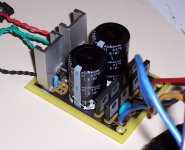
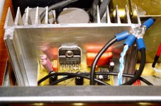
 I'll repost the files in the wee small hours. Speaking of regulators I posted a picture of what has been keeping me from getting to these updates...it's another power supply with regulators. This time its a dual bridge unit (got to be trendy) with LM338 regulators and a good amount of capacitance
  this is NOT for the preamp project, this is actually the new PSU for my LM4780 amp project.
It's running of a Plitron 750VA toroid..mmmm power!
Attachments
Member
Joined 2002
Corrected Layouts
Uhhh...nope, it's a double sided board, the large black area is actually not connected to anything. There were a few points that I had to solder on the top and bottom of the board since this is DIY and I can't plate my own through holes...yet 😀
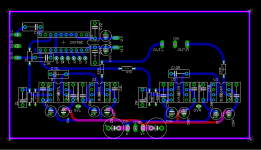
Anyway I finally updated the board files I have attached them here. The routing is actually a bit better now that the errors are fixed....and I updated the parts names. No SCH yet, I'll work on that later too...but Pavels schematic is good if you change the pinout of the BUF634 to match the DIP8 package.
Have Fun! 😉
jleaman said:How come all the traces are on the top ? Forgot to flip the image when etching ?
Uhhh...nope, it's a double sided board, the large black area is actually not connected to anything. There were a few points that I had to solder on the top and bottom of the board since this is DIY and I can't plate my own through holes...yet 😀
Anyway I finally updated the board files I have attached them here. The routing is actually a bit better now that the errors are fixed....and I updated the parts names. No SCH yet, I'll work on that later too...but Pavels schematic is good if you change the pinout of the BUF634 to match the DIP8 package.
Have Fun! 😉
Attachments
Member
Joined 2002
Does this program use the eagle files and make this 3d stuff ? Im going to try this now. Thanks.
J'
J'
To Gcolier : Your PCB's are extraordinary pretty, you have talent for aesthetic feeling 😎 . I have only little notices : make around holes for fitting more space without copper, remember on head of screw and insulating distance - not on every cases you need grounding at this point. Make instead second serial regulator rather capacity multiplier. It is practical noisless and for this aplication much more efficient. If you can make this for PA, make this with darlington. 😉
jleaman said:Does this program use the eagle files and make this 3d stuff ? Im going to try this now. Thanks.
J'
Yes it does! You need to download Eagle 3D and also POVRAY. Both are free! One thing that I found...dont use a + in ay component name. Also you need to select the option that allows you to select replacement components if the one you have on your board doesn't have a 3D model.
Good Luck!
😀
Upupa Epops said:To Gcolier : Your PCB's are extraordinary pretty, you have talent for aesthetic feeling 😎 . I have only little notices : make around holes for fitting more space without copper, remember on head of screw and insulating distance - not on every cases you need grounding at this point. Make instead second serial regulator rather capacity multiplier. It is practical noisless and for this aplication much more efficient. If you can make this for PA, make this with darlington. 😉
Upupa: Thanks for the compliments! I try 😉
Could you explain a little about the capacity multiplier...a schematic for this from after the LM3xx's if possible (a picture is worth a thousand words...especially when we don't speak the same language 😉 )
Also I'm not sure which screws you are refering to...the ones that will hold the TO220's to the board...or the ones for the standoffs? As for the TO220's I was going to use insulated washers or even nylon screws (I cant imagine I need a tonne of holding power here. As for bare space around the holes...I will need to adjust the isolation distance...also likely spread out the components a little as I keep cutting apart my ground bus when doing this.
Thanks for the help!
I was refering about holes for standoffs. Capacity multiplier you get, if you change zener diode by capacitor. 😎
Hey I found a great tool today called Eagle 3D!
Gcollier, those renderings looks great🙂
Nelson Pass wrote about a regulated supply with capacitance multiplier in the Zen variations part 3, Also Rod Elliot made an article on the subject. See these two links:
http://sound.westhost.com/project15.htm
http://www.passdiy.com/pdf/zen-ver3.pdf
Steen🙂
Re: Teasers
I have been insisting with this for years...
Pin 7 is V+ on the OPA627/37.
The same on the BUF634.
Why do you put the two electrolythics on the same side?
One rail (V-) is fine, the other one (V+) is not.
The board looks good, but it won't sound as good as it could.
That simulation tool is great.😉
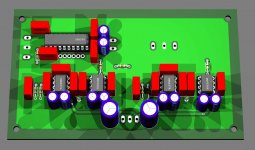
Gcollier said:Hey I found a great tool today called Eagle 3D! It lets you render eagle boards using POVRAY. Here is the preamp board....I need to tinker a bit to figure out how to adjust the viewpoint, but this is a great tool to help visulaize a board!
I have been insisting with this for years...
Pin 7 is V+ on the OPA627/37.
The same on the BUF634.
Why do you put the two electrolythics on the same side?
One rail (V-) is fine, the other one (V+) is not.
The board looks good, but it won't sound as good as it could.
That simulation tool is great.😉
Re: Re: Teasers
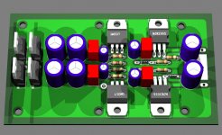
Carlos: You must be looking at my initial board design before I made the correction (thanks to Jleaman). I posted the Eagle BRD files for the new one a few posts ago....here is a shot of how everything looks minus the groundplane. I don't follow what you are saying about the electrolytics...are you referring to the two at the bottom of each OPA and BUF chip...they just seem to fit there so nicely 😉 So looking at the picture I just posted here, what suggestions do you have for improving the sound?
Steeno: I looked at the info on Rod Elliots site regarding the Capacitance multiplier last night, I'll download the Pass article and go through it too. What's the consensus out there...zener or capacitance multiplier in the PSU? As I understand from Rod Elliot's article if the capacitance multiplier is not done right it can get really noisy...something I am trying to achieve the complete opposite of.
Anyway have at the modifierd preamp board. (also notice the caps on the input before the DS1802...you could put these in or just jumper it if you prefer.
carlosfm said:
I have been insisting with this for years...
Pin 7 is V+ on the OPA627/37.
The same on the BUF634.
Why do you put the two electrolythics on the same side?
One rail (V-) is fine, the other one (V+) is not.
The board looks good, but it won't sound as good as it could.
That simulation tool is great.😉
Carlos: You must be looking at my initial board design before I made the correction (thanks to Jleaman). I posted the Eagle BRD files for the new one a few posts ago....here is a shot of how everything looks minus the groundplane. I don't follow what you are saying about the electrolytics...are you referring to the two at the bottom of each OPA and BUF chip...they just seem to fit there so nicely 😉 So looking at the picture I just posted here, what suggestions do you have for improving the sound?
Steeno: I looked at the info on Rod Elliots site regarding the Capacitance multiplier last night, I'll download the Pass article and go through it too. What's the consensus out there...zener or capacitance multiplier in the PSU? As I understand from Rod Elliot's article if the capacitance multiplier is not done right it can get really noisy...something I am trying to achieve the complete opposite of.
Anyway have at the modifierd preamp board. (also notice the caps on the input before the DS1802...you could put these in or just jumper it if you prefer.
Attachments
Re: Re: Re: Teasers
Yes.
I suppose this is an audio forum, right?
Audio should be a main issue, not just a pretty looking board.
They "fit" so nicely because you have done it that way.
Don't worry, the way you have done is the most common to see on commercial gear.
Gcollier said:are you referring to the two at the bottom of each OPA and BUF chip...
Yes.
Gcollier said:they just seem to fit there so nicely 😉
I suppose this is an audio forum, right?
Audio should be a main issue, not just a pretty looking board.
They "fit" so nicely because you have done it that way.
Don't worry, the way you have done is the most common to see on commercial gear.
Re: Re: Re: Re: Teasers
Carlos: I'm actually working on this board right now. And of course asthetics is not my main concern...but if it doesn't look good how good can it sound, I mean really...we all know how terrible P2P gainclones sound rght 😀 LOL Anyway, I suspect you are suggesting that I move the V+ caps to the upper side of the chips to be closer to pin 7. I would do this but it makes the routing kind of messy, also with the way I have it now the "power section" of the board is all at the bottom well isolated from the input and output...and yes I know there are power traces only a few mm away from the in and out pins 😉 For now I'll keep on working on cleaning up the supply rails.
carlosfm said:
Yes.
I suppose this is an audio forum, right?
Audio should be a main issue, not just a pretty looking board.
They "fit" so nicely because you have done it that way.
Don't worry, the way you have done is the most common to see on commercial gear.
Carlos: I'm actually working on this board right now. And of course asthetics is not my main concern...but if it doesn't look good how good can it sound, I mean really...we all know how terrible P2P gainclones sound rght 😀 LOL Anyway, I suspect you are suggesting that I move the V+ caps to the upper side of the chips to be closer to pin 7. I would do this but it makes the routing kind of messy, also with the way I have it now the "power section" of the board is all at the bottom well isolated from the input and output...and yes I know there are power traces only a few mm away from the in and out pins 😉 For now I'll keep on working on cleaning up the supply rails.
Re: Re: Re: Re: Re: Teasers
Right.
That's your choice.
Or you do it properly, or simply don't use good/fast op-amps.
The OPA627 doesn't sound decent that way.
If I would decide on the pinout of an op-amp, V+ would be at pin 5 and I would use the caps as you did.
But unfortunately nobody thought about that decades ago, and the chips back then didn't demand that, anyway.
My mini-"Krell".😀
Gcollier said:Anyway, I suspect you are suggesting that I move the V+ caps to the upper side of the chips to be closer to pin 7.
Right.
Gcollier said:I would do this but it makes the routing kind of messy, also with the way I have it now the "power section" of the board is all at the bottom well isolated from the input and output...
That's your choice.
Or you do it properly, or simply don't use good/fast op-amps.
The OPA627 doesn't sound decent that way.
If I would decide on the pinout of an op-amp, V+ would be at pin 5 and I would use the caps as you did.
But unfortunately nobody thought about that decades ago, and the chips back then didn't demand that, anyway.
My mini-"Krell".😀
Attachments
- Status
- Not open for further replies.
- Home
- Amplifiers
- Chip Amps
- GC Preamp Suggestions