I am looking to build a multichannel preamp for a 5+ channel gainclone, this will be for home theater use. My plan so far is as follows:
Source Selector: switch ripped from an old parallel port switch (easily modified...plenty of channels!)
Digital pot for each channel: DS1802
Input Buffer: BUF634
Gainstage: OPA637
this is similar in design to this post: http://www.diyaudio.com/forums/showthread.php?postid=197061#post197061
I have used the DS1802 before and am quite satisfied with the sound, and also with the ease with which it can be implemented.
I have not worked with input buffers before but figure this would make a good first gain stage to feed into the OPA637. I have never used OPA637 before either but I have done plenty with OPA134.
This will most likely be feeding 5+ channels of parallel LM4780.
Anyone who wants to help with the this design please feel free....unless you are going to suggest tubes
Thanks
I'm currently building something very similar. I'm doing differential inputs with the INA136, volume control with the PGA2311, and diff output to drive bridged 4780s with OPA1632. Input selection is with relays, using the double pole trick to eliminate crosstalk.
The whole thing is going to be run by a Cygnal C8051F320 microcontroller (because thats what I'm using at work). I'm putting a 16x2 LCD on the front for input / volume indication. Channel by channel trim, for each input, stored in Flash on the micro. Might also try my parental lock idea - a PIN code limits the volume to a settable level. Just so teenagers can't have loud parties while you're out!
The whole thing is going to be run by a Cygnal C8051F320 microcontroller (because thats what I'm using at work). I'm putting a 16x2 LCD on the front for input / volume indication. Channel by channel trim, for each input, stored in Flash on the micro. Might also try my parental lock idea - a PIN code limits the volume to a settable level. Just so teenagers can't have loud parties while you're out!
Preamp Suggestions
Wow! Sounds like one heck of a project! I was also looking at PGA2311 but since I have no experience with PIC programming I am relegated to DS1802...which really isn't that bad! I must admit the idea of a PIN to lock out the volume control is interesting...I've got 4 year old triplets...imagine the wild parties when they are 16...yikes Anyway if you have any pics/schematics of your project , or suggestions for caps/resistors etc to use in the signal path I'd be interested. I'm trying to keep the price point down, but still wan't reasonable quality.
TwoSpoons said:I'm currently building something very similar. I'm doing differential inputs with the INA136, volume control with the PGA2311, and diff output to drive bridged 4780s with OPA1632.
Wow! Sounds like one heck of a project! I was also looking at PGA2311 but since I have no experience with PIC programming I am relegated to DS1802...which really isn't that bad! I must admit the idea of a PIN to lock out the volume control is interesting...I've got 4 year old triplets...imagine the wild parties when they are 16...yikes
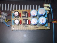
Anyway if you have any pics/schematics of your project , or suggestions for caps/resistors etc to use in the signal path I'd be interested. I'm trying to keep the price point down, but still wan't reasonable quality.I did quickly put together a preamp like CarlosFM's in the above mentioned thread. I was amazed with the sound🙂 That was surely a very nice experience! It was a bit too analytic, for my taste though. Everything is so clearly cut, that I have never heard anything like it. One advice, take CarlosFM's saying about the OPA's likes capacitance seriously. I had 100uF right at the pins of the OPA's. I do not think tube guys find this one very musical though! This is not based on long time listening, just based on comparison with my normal setup. (BosoZ) 🙂
Have a look at my perfboard.
Steen.
Have a look at my perfboard.
Steen.
Attachments
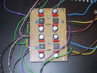
Hate to quote myself, BUT this is actually Pavel Macura's circuit.I wanted to test CarolsFM's ideas!
Sorry Pavel. Known as PMA on this forum. But CarlosFM did bring it to our attention, on a bigger scale😉 Hope none is offended😎
All the best
Steen.
I'll Look That Up
I'll have to do a search on this circut. I'm not sure what to think about this circut sounding so "precise" I guess that could be a good thing since this is intended to be a home theater preamp. I actually used a CMOY headphone amp based on an OPA134 to drive an LM3875 gainclone and found that something "magical" happened with the sound...of course it could have just been the fact that I was bypassing the dreadful opamp in the portable CD player I was using as a source.
steenoe said:
Hate to quote myself, BUT this is actually Pavel Macura's circuit.
Sorry Pavel. Known as PMA on this forum. But CarlosFM did bring it to our attention, on a bigger scale😉 Hope none is offended😎
All the best
Steen.
I'll have to do a search on this circut. I'm not sure what to think about this circut sounding so "precise" I guess that could be a good thing since this is intended to be a home theater preamp. I actually used a CMOY headphone amp based on an OPA134 to drive an LM3875 gainclone and found that something "magical" happened with the sound...of course it could have just been the fact that I was bypassing the dreadful opamp in the portable CD player I was using as a source.
I have not worked with input buffers before but figure this would make a good first gain stage to feed into the OPA637
Is there any reason to do this instead of using the OPA637 to feed the buffer? I am trying to understand preamp design since I'm planning on building one of my own. I typically see the 637 feeding a buf634, which acts as a current amplifier I think. I figure this is because the 637 has low output current? 😕 What would be the advantage of putting the buffer first?
I think the magic here is the result of the precision of 627 and current capability of 634.
I build my preamp according to carlos recommendations, and yes, this is good. The bypass is important to make sure no oscillation happens, which practicaly ruins a good opamp performance. Although overall I prefer tube preamp, this is the best SS preamp there is.
neat work, steenoe!
I build my preamp according to carlos recommendations, and yes, this is good. The bypass is important to make sure no oscillation happens, which practicaly ruins a good opamp performance. Although overall I prefer tube preamp, this is the best SS preamp there is.
neat work, steenoe!
Here is the link to the original circuit:
http://www.pha.inecnet.cz/macura/buffer_en.html
I have bought two of Pavel's really cute Pcb's, and will actually build one to keep for myself. I intend to use as much of CarlosFM's
recommendations as possible on the small boards. One will be used as Linestage the other for a headphone amp. I am planning on making a RIAA also, so that this will end up as a complete mini preamp.
Steen.
Whoops...had it backwards
No reason I can think of, in fact I had it backwards in my initial post
Anyway, does anyone have any thoughts on biasing the OPA637 into class A using Pavels design?
Also on another note I was looking at the DRV134 datasheet last night, particularly the Single Ended operation schematic. Any thoughts on running 4 or 5 of these in series, each one feeding the next (Gain of 2). As far as I can see i would need only the one 600 ohm resistor from +out to ground for each DRV134, then I would tie the output of each into the input of the next. The negative outputs are all tied to GND. Any thoughts?
Thanks
scone said:
Is there any reason to do this instead of using the OPA637 to feed the buffer? I am trying to understand preamp design since I'm planning on building one of my own. I typically see the 637 feeding a buf634, which acts as a current amplifier I think. I figure this is because the 637 has low output current? 😕 What would be the advantage of putting the buffer first?
No reason I can think of, in fact I had it backwards in my initial post
Anyway, does anyone have any thoughts on biasing the OPA637 into class A using Pavels design?
Also on another note I was looking at the DRV134 datasheet last night, particularly the Single Ended operation schematic. Any thoughts on running 4 or 5 of these in series, each one feeding the next (Gain of 2). As far as I can see i would need only the one 600 ohm resistor from +out to ground for each DRV134, then I would tie the output of each into the input of the next. The negative outputs are all tied to GND. Any thoughts?
Thanks
One of the simplest ways to bias an Opamp into class A is, to place an diode between the output and the -v supply, this keeps the output of the opamp "high".
Meaning there it is constantly drawing a current, so it is always fully "primed".
More on biasing opamps can be found on here on Tangent's site
Although in Korean, u can see many deigns and test reults on Constant Current Sources (CCS) fom sijosae. Here is the
L'inquage
Meaning there it is constantly drawing a current, so it is always fully "primed".
More on biasing opamps can be found on here on Tangent's site
Although in Korean, u can see many deigns and test reults on Constant Current Sources (CCS) fom sijosae. Here is the
L'inquage
Tangent's Site
I was looking at Tangents site yesterday, lots of good information, in fact I had been considering the Meta42 as a possibility, obviously I might need to tinker with the gain a bit to keep the OPA637 stable. Does placing a diode from V- to out not draw a bit too much current? I had read in another thread that using a resistor from v- to out seems to work well with OPA637, I may try that first then go the transistor route. What I need to do now is work out some schematics draw up a board in Eagle. If anyone want's to help feel free!
n00beR said:One of the simplest ways to bias an Opamp into class A is, to place an diode between the output and the -v supply, this keeps the output of the opamp "high".
Meaning there it is constantly drawing a current, so it is always fully "primed".
More on biasing opamps can be found on here on Tangent's site
L'inquage
I was looking at Tangents site yesterday, lots of good information, in fact I had been considering the Meta42 as a possibility, obviously I might need to tinker with the gain a bit to keep the OPA637 stable. Does placing a diode from V- to out not draw a bit too much current? I had read in another thread that using a resistor from v- to out seems to work well with OPA637, I may try that first then go the transistor route. What I need to do now is work out some schematics draw up a board in Eagle. If anyone want's to help feel free!
There is a couple of very good preamp designs in this forum , one by Alcaid found here
and another good layout by carlosfm, found here .
If you do a search for OPA627 preamp there are many threads that you will find usefull.
I'm working on my own OPA637, BUF634 design but have not got very far.
Im planning on biasing the 637 into class A, as well as having a buffered ground.
I dont know the advantage of a buffered ground in a preamp, but it works well and it is commonly found in headphone amplifiers (Im planning on using the same design as a preamp and a headamp).
Good luck with your designa nd keep us posted.
Craig
Gainclone Preamp
I read through the threads you mentioned (in fact before I started this one). To me Pavel Macura's circut looks the most appealing, but I will be using OPA637 rather than OPA627 and will need to adjust the gain accordingly. Also I will likely bias the OPA627 into Class A, maybe just the resistor as Carlos suggests, but will likely go with another c.c.s approach. I was working las night on a PCB layout using Pavel's schematic, I'll post it when it is finished, I'm finding it a pain to add the decoupling caps.
As for the amps with a buffered ground, I have seen that a lot myself on Headwize etc, but was under the impression that it would only be a benefit to headphones, and could actually be a detriment when feeding a power amplifier.
n00beR said:
Im planning on biasing the 637 into class A, as well as having a buffered ground.
I dont know the advantage of a buffered ground in a preamp, but it works well and it is commonly found in headphone amplifiers (Im planning on using the same design as a preamp and a headamp).
Craig
I read through the threads you mentioned (in fact before I started this one). To me Pavel Macura's circut looks the most appealing, but I will be using OPA637 rather than OPA627 and will need to adjust the gain accordingly. Also I will likely bias the OPA627 into Class A, maybe just the resistor as Carlos suggests, but will likely go with another c.c.s approach. I was working las night on a PCB layout using Pavel's schematic, I'll post it when it is finished, I'm finding it a pain to add the decoupling caps.
As for the amps with a buffered ground, I have seen that a lot myself on Headwize etc, but was under the impression that it would only be a benefit to headphones, and could actually be a detriment when feeding a power amplifier.
Preamp PCB Layout
Ok so here is my "alpha" PCB layout for one channel of OPA637/BUF634 preamp. For a schematic please refer to Pavel Macura's design mentioned in one of the previous posts. The difference here is that I am thinking of using an LM337 voltage regulator as a constant current source, feeding 15mA to the output, which should bias everyting class A. You will notice that, as displayed, I have star grounded everything, in actual fact the blue border on the outside is actually a groundplane that I have hidden. I'm not too sure about using a groundplane here, if anyone has any thoughts on this let me know...it's supposed to be a preamp, not a radio. Also let me know if you have any additional thoughts suggestions on the biasing. 🙂 I will be making this on double sided PCB so there will also be a plane on the topside, but it will not be connected to anything...possibly the chassis ground.
Ok so here is my "alpha" PCB layout for one channel of OPA637/BUF634 preamp. For a schematic please refer to Pavel Macura's design mentioned in one of the previous posts. The difference here is that I am thinking of using an LM337 voltage regulator as a constant current source, feeding 15mA to the output, which should bias everyting class A. You will notice that, as displayed, I have star grounded everything, in actual fact the blue border on the outside is actually a groundplane that I have hidden. I'm not too sure about using a groundplane here, if anyone has any thoughts on this let me know...it's supposed to be a preamp, not a radio. Also let me know if you have any additional thoughts suggestions on the biasing. 🙂 I will be making this on double sided PCB so there will also be a plane on the topside, but it will not be connected to anything...possibly the chassis ground.
Attachments

If you want to bias the buf634 with 15mA, you should consider the 634T version that can be heatsinked, as it is in to220 case. Not sure the DIP8 on your pcb will take the heat.Also let me know if you have any additional thoughts suggestions on the biasing.
Steen.
Re: Preamp PCB Layout
Isn't the normal way to do it to draw the current from the opamp's output to the negative rail? Not feed the current.
Check this out:
http://www.headphoneamp.co.kr/bbs/zboard.php?id=diy_sijosae&no=211
Lot's of CCS examples. Text is not in english but you get the schematics and numbers...
Gcollier said:...The difference here is that I am thinking of using an LM337 voltage regulator as a constant current source, feeding 15mA to the output, which should bias everyting class A...
Isn't the normal way to do it to draw the current from the opamp's output to the negative rail? Not feed the current.
Check this out:
http://www.headphoneamp.co.kr/bbs/zboard.php?id=diy_sijosae&no=211
Lot's of CCS examples. Text is not in english but you get the schematics and numbers...
Beat you to it Alcaid, post is further up the page 😛
One of the simplest ways to bias an Opamp into class A is, to place an diode between the output and the -v supply, this keeps the output of the opamp "high".
Meaning there it is constantly drawing a current, so it is always fully "primed"
More on biasing opamps can be found on here on Tangent's site
Although in Korean, u can see many deigns and test reults on Constant Current Sources (CCS) fom sijosae. Here is the
L'inquage
- Status
- Not open for further replies.
- Home
- Amplifiers
- Chip Amps
- GC Preamp Suggestions