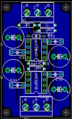
Thanks a lot, MaxW. Nice board🙂 If this is gonna end up with a GP as G. set out to do, we have to make a decision at this point😉
What layout do you guys want?? If this is gonna result in some kind of GP, more of you guys have to attend😉 Please express your thoughts😉
Steen.😎
What layout do you guys want?? If this is gonna result in some kind of GP, more of you guys have to attend😉 Please express your thoughts😉
Steen.😎
Finish etching my stereo board.
It doesn't look like much, but hey its the first thing I have ever etched. 🙂 I will populate it and test it tonight. I will be offering a group buy for this circuit as I have already recieved about 20 emails asking for it. 😀 And I have not even tested it yet! 😱 😉
I was a little off aligning the silkscreen. I did not use transpancy, just photo paper.
An externally hosted image should be here but it was not working when we last tested it.
An externally hosted image should be here but it was not working when we last tested it.
Great work, Russ😎 I did use transparencies for the Components! Easier to put in the right place! Also, the component side doesnt need so much heat, It will blurr
The Copper side, needs a lot of heat, though!!
Steen😎
The Copper side, needs a lot of heat, though!!
Steen😎
Thanks Steenoe. Yeah, I will etch another one tomorrow. I learned a lot from this first one. I don't have any laser transpancies around the house today, So I made do. Since I knew know one else would have to use this PCB. 🙂
Russ, YGM😀
Steen😎
BTW. It seems I will not have time to test your layout at this moment I have too much to attend to😱
Steen😎
BTW. It seems I will not have time to test your layout at this moment
I have too much to attend to😱steenoe said:Russ, YGM😀
Hi steenoe, my mail server took a dump last night. I hope you got my reply. 🙂
Yes I did🙂Hi steenoe, my mail server took a dump last night. I hope you got my reply.
Steen.
This is for a little mixer/headphone amp. it is based on the circuit from this thread, but a few minor changes, it will be switchable between 50 ohm cable driver and headphone amp
I need a few more parts for the PSU board before i can test it. the PSU output is a little high to use without regulators (+ - 19v ac from 14vac wall wart transformer )
I think the amount of time i saved by not making a circuit board was wasted figuring out how to put everything on the rat shack mini board. dont do it 🙂
Attachments
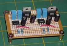
OK, I have finished building an testing this preamp. 🙂 Here are some pics. It works great! 
For my testing since I knew my source was very quiet(no RF noise) and had no DC I simply jumpered C3/C4 and C1/C2. I have a simple audio taper 10K stereo pot on inputs.
I used 10ohm 1% for the output resistor(R9,R10) for all tests.
I used 550ohm 1% for the input resistor(R1,R2) for all tests.
I used 220K (well matched) 5% for input to ground (R3,R4).
All feedback resistors are metal film 1%
For kicks I tried two different types of electrolytics for the bypass caps.
1) 47uf 35V low leakage types. Which were OK(better than nothing), but I found that the midbass really lost its edge.
2) 47uf 35V very low ESR Nichicon which were much much better in every regard!!! I am sticking with these. 🙂
The .1uf bypass caps are some polyester metalized film caps I picked up while back. They sound great. I also used Wima MKPs and did not notice any difference at all. So I am sticking with the originals. They are about half the cost too!.
For unity gain tests I used R5/6 of 4.7 K and R7/8 of 4.7K.
For G=3 tests I used R5/6 of 2 K and R7/8 of 4K.
For G=6(approximate) tests I used R5/6 of 1 K and R7/8 of 4.7K.
I succesfully tested:
OPA627 - gains of 1, 3 ,and 6
OPA637 - gains 3(worked fine evene though spec G=5 min), and 6
OPA227 - gains of 1, 3, and 6
OPA228 - gains of 3 (also worked fine), and 6
LT1115 - gains of 1, 3 ,and 6
LT1028 - gains of 1, 3 ,and 6
AD8610 - gains of 1, 3 ,and 6
This is one VERY transparent pre. I am extremely happy with it.
This simple circuit makes a great headphone amp if you keep the Zout low especially at the lower gain (When connected to my SACD player unity gain was best). Sound got really thin when I increased Zout. Sound was best with straight wire.
Here are two pics, the first is the PCB design, the second the finished pre with +/- 15VDC PS.
Cheers!
Russ
For my testing since I knew my source was very quiet(no RF noise) and had no DC I simply jumpered C3/C4 and C1/C2. I have a simple audio taper 10K stereo pot on inputs.
I used 10ohm 1% for the output resistor(R9,R10) for all tests.
I used 550ohm 1% for the input resistor(R1,R2) for all tests.
I used 220K (well matched) 5% for input to ground (R3,R4).
All feedback resistors are metal film 1%
For kicks I tried two different types of electrolytics for the bypass caps.
1) 47uf 35V low leakage types. Which were OK(better than nothing), but I found that the midbass really lost its edge.
2) 47uf 35V very low ESR Nichicon which were much much better in every regard!!! I am sticking with these. 🙂
The .1uf bypass caps are some polyester metalized film caps I picked up while back. They sound great. I also used Wima MKPs and did not notice any difference at all. So I am sticking with the originals. They are about half the cost too!.
For unity gain tests I used R5/6 of 4.7 K and R7/8 of 4.7K.
For G=3 tests I used R5/6 of 2 K and R7/8 of 4K.
For G=6(approximate) tests I used R5/6 of 1 K and R7/8 of 4.7K.
I succesfully tested:
OPA627 - gains of 1, 3 ,and 6
OPA637 - gains 3(worked fine evene though spec G=5 min), and 6
OPA227 - gains of 1, 3, and 6
OPA228 - gains of 3 (also worked fine), and 6
LT1115 - gains of 1, 3 ,and 6
LT1028 - gains of 1, 3 ,and 6
AD8610 - gains of 1, 3 ,and 6
This is one VERY transparent pre. I am extremely happy with it.
This simple circuit makes a great headphone amp if you keep the Zout low especially at the lower gain (When connected to my SACD player unity gain was best). Sound got really thin when I increased Zout. Sound was best with straight wire.
Here are two pics, the first is the PCB design, the second the finished pre with +/- 15VDC PS.
An externally hosted image should be here but it was not working when we last tested it.
An externally hosted image should be here but it was not working when we last tested it.
Cheers!
Russ
Nice Russ!
You're like a robot spitting out your builds 🙂
Can i ask when you were testing it with headphones wich impedance your headphones have?
I have build peranders QRV-04 (opa627/buf634) and i also can say that without output resistor it sounds best (with 300ohms H-P). Now when i think about it i have a SMD inputcap on that amp and as i know i don't have any DC from my player i'm must try to bypass it 🙂
Russ, there's another test you can make, if you want.
Remove the 47uf electrolythics, leave just the 100nf MKT caps.
Listen.😉
Try the OPA627 and 637 this way.
Remove the 47uf electrolythics, leave just the 100nf MKT caps.
Listen.😉
Try the OPA627 and 637 this way.
Hi Tobias. 🙂 Yeah, I have been particularly motivated the last week or so. 😉 The headphones I used are 90ohms.
Carlos,
I will try your suggestion! I think with the regulated supply that may actually sound very good. I am surprised I did not consider that before.
Thanks!
Carlos,
I will try your suggestion! I think with the regulated supply that may actually sound very good. I am surprised I did not consider that before.
Thanks!
Russ White said:Carlos,
I will try your suggestion! I think with the regulated supply that may actually sound very good. I am surprised I did not consider that before.
Thanks!
I don't expect that to sound good, it's just an exercise for you.😀
Gotcha Carlos, as if I am not doing enough eh. 🙂
Well I did try it for grins. I will keep the Nichicons. 😀 Though really it was not terrible. Better than some of my past headamps (CMOY).
Well I did try it for grins. I will keep the Nichicons. 😀 Though really it was not terrible. Better than some of my past headamps (CMOY).

Russ White said:Well I did try it for grins. I will keep the Nichicons. 😀 Though really it was not terrible. Better than some of my past headamps (CMOY).
Terrible it's not, if you compare to other things.
It's just that the bass dominates, becomes untight and detail goes down a notch.
Latest buffered pre design
I had some time to tinker. If you want to run a buffer biased you really should use the TO220 package, so I did here. I also left plenty of space for a heatsink as you will verly likely need it.
I used the LT1010 simply because I like it a lot. I find it equal in my testing to the BUF634, yet it is less expensive and easier to obtain.
This design should work for just about any single opamp.
It would make a great headphone amp, and will pump out 150+ ma. easily.
Any feedback?
BTW the jumper is there for insurance. I probably will not need it, but I wanted pads there just in case.
Don't laugh I am still a n00b!
Cheers!
Russ
Here is the schma too:
I had some time to tinker. If you want to run a buffer biased you really should use the TO220 package, so I did here. I also left plenty of space for a heatsink as you will verly likely need it.
I used the LT1010 simply because I like it a lot. I find it equal in my testing to the BUF634, yet it is less expensive and easier to obtain.
This design should work for just about any single opamp.
It would make a great headphone amp, and will pump out 150+ ma. easily.
Any feedback?
BTW the jumper is there for insurance. I probably will not need it, but I wanted pads there just in case.
An externally hosted image should be here but it was not working when we last tested it.
Don't laugh I am still a n00b!
Cheers!
Russ
Here is the schma too:
An externally hosted image should be here but it was not working when we last tested it.
- Status
- Not open for further replies.
- Home
- Amplifiers
- Chip Amps
- GC Preamp Suggestions