Try here for a motorised Alps.... you can get 20K.
http://www.hificollective.co.uk/components/potentiometers.html
Peter Daniel is selling some 50K Alps motorised for a low price.
http://www.diyaudio.com/forums/showthread.php?s=&threadid=57626
http://www.hificollective.co.uk/components/potentiometers.html
Peter Daniel is selling some 50K Alps motorised for a low price.
http://www.diyaudio.com/forums/showthread.php?s=&threadid=57626
Hi,
yeah i saw them on hifi collective, bit pricey and the 'blue beauty' one are 70 mm long. Too long for my case.
Is sticking a 20k resisor in series with the pot a really bad idea. That should give me 16.7k. The onlt thing is my pot is log and i gues this will act like a law-faking one so i might get a weird curve on the volume control.
Might try it anyway. Hardly expensive and might be worth a go.
Fil
Have a look at this page on the Leach amp and down near the bottom he shows a method of to make a lower resistance pot by connecting a resistor between input and wiper terminal. I've never tried it but someone here might be able to tell us how successful it is.
http://users.ece.gatech.edu/~mleach/lowtim/part2.html
http://users.ece.gatech.edu/~mleach/lowtim/part2.html
Thanks a lot,
Pretty much what i had planned to but maybe i have the wrong values.
I cant see it can do much harm (fatal last words). Just remove them if if doesnt help.
I was going to use 20k so that 20k*100k / 20k+100k equals 16.67k which sounds ideal.
Best bite the bullet as see.
Also all the bits for my 'Nuuk' active stage and psu arrived today.
Good god those 4.7uf poly caps are huge!!!
How the hell am i going to fit some of them in my cd player?
Anyway christams came early.
fil
I would sujest using the buffering both sides of the pot. This would make it a universal preamp suitable for all situations. The single power supply should cope with both easily, and the circuit is so simple and small that finding room for it shouldn't be a real issue.
First off i would see how it sounds with the pot you have and without modification - you might find everything hunky dory with the buffer added.
Shoog
First off i would see how it sounds with the pot you have and without modification - you might find everything hunky dory with the buffer added.
Shoog
filholder said:Good god those 4.7uf poly caps are huge!!!
By the way, the quality of this part is important. It is a good place for a boutique type cap.
I got some from Maplin that Nuuk had previously recomended for the input caps on my gain clone. They arent particularly cheap at £4 a peice. Should do for a starting point anyway.
Fil
Fil
I'm still happy with the preamp! 🙂
I fitted a second discrete regulator so that the two buffers are fed separately, but did not notice any obvious differences between that and single supply.
So now I have an extra regulator. That's why I am happy to see Shoog's suggestion of putting extra buffers before the pot 🙂
What do you guys think, should there be a capacitor on the output of the buffer before the pot, too? Will the DC offsets add up and become too much (or whatever bad) otherwise?
Filholder: You are right! Normally you put it after the pot, but I want to act on Shoog's suggestion of putting a buffer in front of the pot in addition to the one which is already positioned after the pot 🙂 Didn´t want to confuse anyone, sorry 🙂
Sorry i should have got that, you are talking about a twin buffer situation. All makes sense now.
Thanks,
Fil
Thanks,
Fil
Filholder: My limited knowledge in the English language makes it tough for me to explain what I mean in a consice way. Thanks for clarifying my post, "twin buffer" thats an excellent way of putting it 🙂
No problems at all.
Sorry i am very new to all this so can i clarify something.
I have nearly finished the PSU and am starting to think about the actual buffer circuit.
On Nuuks diagram for the buffer circuit you have a +15 and a -15v and a ground. The ground i presme is the 0v on the psu board. What i dont understand is the ground for the input and output. Are these also connected to the power ground or do just connect together as in only the input and output go to through the buffer and the grounds just connect together.
Sorry now my english is failing me as well as my experience at this type of thing.
Fil
Attachments
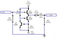
All grounds are to be wired together. The ground is always common. Sometimes ppl are talking about power ground and signal ground, but that is all just about which order to connect stuff to the common ground. The grounding order of this preamp does not seem to matter though.
So the signal ground wires of both input and output would be connected to the 0v line on this diagram. Actually they would be connected after the second stage of regulation but you see what i mean.
Thanks for your help by the way, i find grounding the hardest part of all this stuff, seem to get confusing very quickly.
FIl
Thanks for your help by the way, i find grounding the hardest part of all this stuff, seem to get confusing very quickly.
FIl
Attachments
Good to seeyour making progress.
I personally am not certain you will get much of a benefit from the buffer before the POT, I think there is a potential for it to sound just as good without it. I would incorperate some simple method of bypassing it to see which you prefer. I for one would be interested in the result as I was contemplating this myself but never got around to it.
Shoog
Hi Ahoog,
Do you mean bypassing the pot with the resistors to lower the resistance? I will defintely try this in the next couple of days. Been very busy at work so time on the project is limited at the moment. However Nuuks PSu was very easy to build, did most of it in a night. Just need to test out the output from the rectifier before i connect it to the cascade of caps i have already wired up.
Fil
No I mean bypass the first buffer before the pot. Adding in the buffer before the pot also adds in an extra cap in the signal path - you may just find that the improvement gained by having the first buffer is then waisted in going through the extra cap. Theres no easy way of knowing without actually trying it in both configeration, therfore I advocate a bypass for the first buffer so that you can make an empirical judgment for yourself.
Don't take anyones word for the benefits to be achieved from one implementation over another. Their experience and taste may be completely different from your own. I would value your own experience above all.
Shoog
Don't take anyones word for the benefits to be achieved from one implementation over another. Their experience and taste may be completely different from your own. I would value your own experience above all.
Shoog
- Status
- Not open for further replies.
- Home
- Amplifiers
- Chip Amps
- GC passive pre-amp dissapointment