tommak said:I'm also interested!
Does anyone know if this will work well with the Corning pH meter Model 7 meters you can buy on eBay?
I searched the EDN site and found Jon Munson's article on the above design. ( Then I saw that jackinnj also linked to this in another thread. )
http://www.edn.com/contents/images/6280030.pdf
Thanks,
Tom
I have a couple of those Corning meters -- they use tubes -- they are exactly the type I used when doing analytical and quantitative chemistry over 30 years ago.
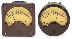
Nordic said:I'd be interested if you can help me with a method to test VU meter rateings... I have a few sets pirated from miscelaneous pieces of amps and tapedecks...
The meter movement is driven by the current flowing in its coil -- you have to determine the amount of current which drives the meter to full scale -- as shown in the attached, choose a potentiometer whose value is twice that necessary to cause the meter to deflect to full scale. In the case of a 50uA meter and 1.5V battery a 100k potentiometer will work. The shunt potentiometer should be about 1k -- this method is described in the ARRL handbook.
Attachments

ah ok, small voltage + ohms law and observe swing on needle.... it is a DC voltage though that I need to apply?
ok, here's a 3D image of what the board looks like -- two channels -- 5" x 2" -- I am going to make a proto to make sure that they work. You can make your own 10mH inductors or purchase from Mouser:
An externally hosted image should be here but it was not working when we last tested it.
jackinnj,
Only one comment to your layout: why do you have so much space/air round components ? This board could be halves the size to what it looks to be now by placing the on board components tight and closer together. This will make the board more flexible to use in amps where there is not much space to fit a board including one VU-meter (mono block amp), or worth, one board and two VU-meters (stereo amp). If using this board in a pre-amp or in a mixer, ok, there is usually space enough for this, but seldom in a power amp due to the "big" VU-meters you had to mount if visibility should be good enough. Also there should be a power supply to feed this VU-board, an extra placing issue.
Just some thoughts
Otherwise it looks great.
Regards 😎
If I had "Autoplace" I could probably fit it into 3/4's the space -- bur my poor addled brain can't take the strain.
I like to site the mounting holes at least 0.200 inch from the periphery and try my best to keep everything which is defined by their centers into a tight rectangle. I allow for R0207R10 resistors which are a little big for a tiny project. My fingers aren't quite as nimble as they used to be, but I agree -- it could be perhaps 25% smaller.
Jack
Come on Jack, you know you want to make is smaller... small is the new black.
So how long before we can start ordering?
So how long before we can start ordering?
Jack, I need to borrow your brain...
This circuit is for a 3500ohm movement, mine is only 650 ohm.
The instructions says to change R6, 7 & 8. to accommodate other meter resistances. I am at a total loss. My meter moves but is only deflecting the needle a tiny bit, (about one numbered unit) on the scale.
Can you offer guidance my learned solderer.
An externally hosted image should be here but it was not working when we last tested it.
This circuit is for a 3500ohm movement, mine is only 650 ohm.
The instructions says to change R6, 7 & 8. to accommodate other meter resistances. I am at a total loss. My meter moves but is only deflecting the needle a tiny bit, (about one numbered unit) on the scale.
Can you offer guidance my learned solderer.
I might be off bace here but wouldn"t a LED VU meter be cheaper and easier to implement??
There are quite a few designs available for a LED VU meter and there are many IC"s available for controlling The LED"s based on the DB of the input signal....
i know there is a Project and Boards availabel at the Prodigy pro forum and the Boards were only $4 and the Parts weren"t much more expensive......
Cheers
I guess if your Going for the Retro Look then the standard Analogue meters are the way to go but i personally like LED VU meters better as you can arrange the LED"s in cool Patterns to say Spell something or make a Cool design.....
Cheers
Cheers
Then you should buy the other meter driver boards. Folks that want moving needle meters are not much impressed with dancing LEDs.
Might be swimming against the tide on this thread.
Might be swimming against the tide on this thread.
Minion said:I guess if your Going for the Retro Look then the standard Analogue meters are the way to go but i personally like LED VU meters better as you can arrange the LED"s in cool Patterns to say Spell something or make a Cool design.....
Cheers
I wouldn't dissuade you from using the LED Drivers from National -- the schematic I described (with full credit to the folks at LinearTech who thought it up) provides something close to the right attack and delay times with pretty good dynamic range -- see the original EDN article.
I haved been really jammed up with my real job so haven't been able to get the prototypes done.
- Status
- Not open for further replies.
- Home
- Group Buys
- GB -- "VU Meter Amplifier" PCB