@ Tea
Your C2Y method will do. I just couldn't resist to tease with the Shaolin punchline once more. 😀
Your C2Y method will do. I just couldn't resist to tease with the Shaolin punchline once more. 😀
Really sorry to hear. I don't do well with that stuff. Glad you have a new friend.
Is this off topic?😀
I certainty don't care. I only try to push technical questions beyond the kit or sales aspect to the main NJFET build thread. Otherwise newcomers might get confused with no solid topic established. With that said, Pet grief is very real.
My package just arrived safe and sound. Many thanks to both Tea and Salas for making
this adventure possible!
this adventure possible!

Tea-Bag & Salas:
My package also arrived today. I haven't started obsessively pouring through the contents of the individual bags yet, but the pcbs are beautiful!
Thank you both for making this project available!
Regards,
Scott
My package also arrived today. I haven't started obsessively pouring through the contents of the individual bags yet, but the pcbs are beautiful!
Thank you both for making this project available!
Regards,
Scott
The PCBs are really nice!
Quick question: What is the consensus on installing the Q1/Q2 sockets in this version? Seems like a good idea for maintaining the rare JFETs, but also unnecessary because of S5-S8, correct?
Quick question: What is the consensus on installing the Q1/Q2 sockets in this version? Seems like a good idea for maintaining the rare JFETs, but also unnecessary because of S5-S8, correct?
About consensus on practical things it will come from the builders. Just an opinion from my side:
Pure approach is use no sockets because it's the signal path at a weak point. That thinking would mean solder the signal cables too.
Prudent approach is use those sockets and cable terminals until you verify the build in all its settings, at least electrically, wait and remove them some time before box installation to make those 2SK369s and signal cables choices permanent. Just in case you had to change something meanwhile. Unless you aren't good with desoldering.
Here is my Beta test report for assembly, first power up and initial setup:
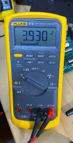
• Nothing special about Raw DC part. Just need to keep output voltage under load in ballpark, as Salas indicated on first page. I used my Electronic Load for 100mA(Thanks to Salas for reminder. I already almost forgot that I have one. It was broken and I repaired it due to that project necessity). I found needed Rd for Raw DC to output 46VDC. You can use power resistor to simulate same load instead.
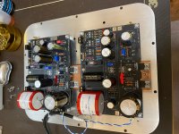
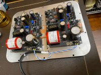
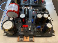
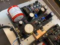
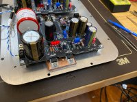
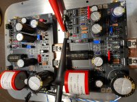
• About Phono… I got all semi, small capacitors and some precision resistors from Tea-Bag (same as kit). All the rest of parts I had in my bin, beside 0.1uF and 2.2uF caps which I acquired within <1% matching from Partsconnexion. Assembly is easy and requires some basic soldering skills. It is very much same level of intricacy as you probably see on all devices designed by Salas. Very low possibility for making mistakes. When all parts are in hands and all matched part are sorted out, the full assembly and final cleaning should take about 2 hours. As you see on my images, I used copper plate for semis. I just made some overkill (since I could use my bottom plate alone), but I decided to be prepared for future 150mA CC setup and test (if I'll decide to try). BTW, I did not connect UntraBIB to Phono yet till I powered UltraBIB first and set its Trimmer for Vout close to 34VCD. Then, I soldered links from UltraBIB power Out to Phono power IN. Powered up all gain and now all (include Phono side) LEDs are lighted up. At that point, I adjusted UBIB again for 34VDC. I noticed that three UBIB LEDs are bit more dim in brightness compare to Phono LEDs. It might scare some of you…. TP voltage was 0 at that point, but turning trimmer clockwise brought me to the needed 4VDC BIOS.
• So, this is it by now and I’ll box it during this weekend. Listening session will be done soon and I’ll report accordingly.
• Nothing special about Raw DC part. Just need to keep output voltage under load in ballpark, as Salas indicated on first page. I used my Electronic Load for 100mA(Thanks to Salas for reminder. I already almost forgot that I have one. It was broken and I repaired it due to that project necessity). I found needed Rd for Raw DC to output 46VDC. You can use power resistor to simulate same load instead.
• About Phono… I got all semi, small capacitors and some precision resistors from Tea-Bag (same as kit). All the rest of parts I had in my bin, beside 0.1uF and 2.2uF caps which I acquired within <1% matching from Partsconnexion. Assembly is easy and requires some basic soldering skills. It is very much same level of intricacy as you probably see on all devices designed by Salas. Very low possibility for making mistakes. When all parts are in hands and all matched part are sorted out, the full assembly and final cleaning should take about 2 hours. As you see on my images, I used copper plate for semis. I just made some overkill (since I could use my bottom plate alone), but I decided to be prepared for future 150mA CC setup and test (if I'll decide to try). BTW, I did not connect UntraBIB to Phono yet till I powered UltraBIB first and set its Trimmer for Vout close to 34VCD. Then, I soldered links from UltraBIB power Out to Phono power IN. Powered up all gain and now all (include Phono side) LEDs are lighted up. At that point, I adjusted UBIB again for 34VDC. I noticed that three UBIB LEDs are bit more dim in brightness compare to Phono LEDs. It might scare some of you…. TP voltage was 0 at that point, but turning trimmer clockwise brought me to the needed 4VDC BIOS.
• So, this is it by now and I’ll box it during this weekend. Listening session will be done soon and I’ll report accordingly.
Attachments

Last edited:

Beautiful. Congrats.
Edit:
Power section's LEDS run well below 5mA on J1's degenerated IDSS, phono section's LEDS mA (and brightness) depending on Q7's free IDSS. J1 must not use high bias because it's exposed to higher voltage than the other JFETs. To avoid life shortening dissipation levels.
Edit:
Power section's LEDS run well below 5mA on J1's degenerated IDSS, phono section's LEDS mA (and brightness) depending on Q7's free IDSS. J1 must not use high bias because it's exposed to higher voltage than the other JFETs. To avoid life shortening dissipation levels.
Tea, Got my package. Arrived in great shape. Thank you and Salas for the work you do to provide DIYers like me with such great products. I can only imagine all the things that go on before hand to have this arrive on my door step so thank you both very much. And, it's organized and labeled so not just a giant grab bag.
One question, for my for the boards part of the project, do I just need the Clarity CMR and Mundorf Evo caps.
Thanks again,
Don
One question, for my for the boards part of the project, do I just need the Clarity CMR and Mundorf Evo caps.
Thanks again,
Don
Alexk: Nice. Very clean and amazingly quick. What process do you use to layout and drill the plate. I am dark ages. Very laborius. I need a better method. Thanks.
Don
Don
Hi Don, thank you for complement. I’m not that fast.. 🙂. It took me about 12 days to get all needed elements to assemble it till I would be able to test it electrically. I use my eyes... 🙂, and nothing else special. I have cheap Chinese table top drill press ($65) from Harbor Freight.
However, I use CNC shope for my front panels. All other location
holes are made by me. I’m lucky since I had my bachelor in mechanical engineering once 🙂.

However, I use CNC shope for my front panels. All other location
holes are made by me. I’m lucky since I had my bachelor in mechanical engineering once 🙂.
Well, you certainly have a knack for getting the "grid" layout down. Me too on the degree but somehow I'm not remembering how that can help me.😀 And, right now I'm wishing it was electrical.😀
Tea-Bag - I received my kit today, very fast shipping, it usually takes a couple of days wondering around the state of Wisconsin before it finds me.
Thank you for all your effort, and please thank Tea jr also.
Thank you for all your effort, and please thank Tea jr also.
One question, for my for the boards part of the project, do I just need the Clarity CMR and Mundorf Evo caps.
Thanks again,
Don
Yes, C3-C4 are not included. C4 will do well being A Mundorf EVO or Clarity CMR for size. C3 probably has more flexibility. My neighbor ran some Russian Teflons that fit in both spots, but then replaced C3 with a Jupiter Copper Foil. It was an improvement for sure over Russian Teflon. Did it embarrass the Clarity CMR C3, not at all IMO. He also had a C3 Silver/Gold/Oil too, sounded as good to my ears, but it was wrong value (1uf, not .1uf) so was removed.
I have several of the Mundorf EVO sets now on hand to test. They are tiny. It will take me time, and I will likely not recommend one over another. I think system synergy and taste get very important here if you want to tweak the sound. But this could take me a while to get around to getting these to pop in and out to compare them. Once I am done, I will offer them out to others to try if interested. This Group Buy took some attention away from other projects I will need to attend to for a bit. Plus everyone is occupying space where I normally listen to music during these times, even my little basement office I share with my wife now. It's where I normally listen to a lot of music while working.
My package isn‘t here yet [emoji22]
It started its journey in kennebunk, went to Jamaica (ok, it‘s Jamaica NY, but „Jamaica“ sounds funnier [emoji907]) and is waiting for snatching a spot on a plane/clearance to cross the ocean...
Nevermind, I never expected to be in the first row of builders, and can benefit from the builds underway! [emoji1303]
Seeing you guys talk C3 C4 coupling caps here's a thing you may come across. Outer foil and where to orient it. Some types may have a side mark or a different lead sleeve color or a shorter lead to indicate it. Should go to the lower impedance side of any circuit.
In UFSP its the incoming signal side having lower impedance. For C3 its towards the board's edge, for C4 its towards the C9 location.
Outer foil good orientation is about capacitors picking minimum interference. Useful in high impedance tube circuits built on tag strips. For modern film caps in solid state usually makes little difference to no difference on scope tests in my experience. On top of that the UFSP board is fully screened. So I don't recommend to lose much sleep over that, but if you got marked caps for orientation, now you know.
Salas helped me to run final electrical test on 1.3S part of new UltFolded to see if 34V is stable and has no oscillation or noise. Please see results here:
https://www.diyaudio.com/forums/analogue-source/129126-simplistic-njfet-riaa-1786.html#post6243071
https://www.diyaudio.com/forums/analogue-source/129126-simplistic-njfet-riaa-1786.html#post6243071
- Home
- Group Buys
- GB Group Buy Salas UltraFSP RIAA