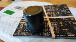
Thanks Tea Bag, my boards arrived today. I really apreciate how thick and sturdy they are. Are those boards US-made?
Looking forward for a weekend of soldering and (hopefully) listening!
Looking forward for a weekend of soldering and (hopefully) listening!
Looks like my reservoir cap ist too big, i will have to bend R1 away from board and solder R2 to the downside of the board. How hot will those resistors get with a total load of 200 mA - 300 mA? Should i wait for a smaller reservoir cap or am i ready to solder this weekend?
Attachments
During these strange times,
If in another group buy I offered more parts to complete board, up to, and including R1 in several values, does this help anyone?
I have had several requests for it in the pasts. It will make you pay more for shipping, but costs are high anyways at this point.
If in another group buy I offered more parts to complete board, up to, and including R1 in several values, does this help anyone?
I have had several requests for it in the pasts. It will make you pay more for shipping, but costs are high anyways at this point.
Parts And Board request
Signed up for(1) Pos kit for SSLV1.3 to make 24vdc supply and (1) L-Adapter Board with (1) full parts kit.
Signed up for(1) Pos kit for SSLV1.3 to make 24vdc supply and (1) L-Adapter Board with (1) full parts kit.
Are there currently any boards and minikits available?
No, please sign up if you can wait for sometime for group buy demand to increase.
Has anyone in the EU received PCBs sent during April
My pcbs were sent on the April 1st and last tracking status is from April 9th - “Processed through regional facility JAMAICA NY”. I know that ordinary postal traffic is cut off between US and EU, but occasionally some packets from US arrive to Croatia. I’m trying to determine is packet definitely lost or just delayed due Covid-19 postal traffic restrictions.
My pcbs were sent on the April 1st and last tracking status is from April 9th - “Processed through regional facility JAMAICA NY”. I know that ordinary postal traffic is cut off between US and EU, but occasionally some packets from US arrive to Croatia. I’m trying to determine is packet definitely lost or just delayed due Covid-19 postal traffic restrictions.
My pcbs were sent on the April 1st and last tracking status is from April 9th - “Processed through regional facility JAMAICA NY”. I know that ordinary postal traffic is cut off between US and EU, but occasionally some packets from US arrive to Croatia. I’m trying to determine is packet definitely lost or just delayed due Covid-19 postal traffic restrictions.
It is difficult to say still. Lets wait a couple weeks. Most have arrived or between returned to me when they close, but 5 or more or lost. a substantial amount way above normal times. If no arrival then, private message me, and I can re-send or refund.
I have received my boards, thanks.
By the way, if the shunts are fed with choke-filtered raw DC, is there any need of Rf?
By the way, if the shunts are fed with choke-filtered raw DC, is there any need of Rf?
I apologize if this has been covered elsewhere, but can I go with a smaller reservoir cap than 6800uf? I’m dealing with a pretty small spot in my chassis and will be stacking my boards. Moreover, it’s a 2U chassis and I have to watch height. The largest cap I can find that meets my needs is 3300uf.
I will have exactly the same, 2U and stacked boards. Maybe you need higher voltage rating, but for 25 V this is fine capacitor that fits and is big enough for a 0,5 A load:
LKG1E472MESZAK Nichicon | Mouser
LKG1E472MESZAK Nichicon | Mouser
Thanks for sharing! That could be a good option, though I’ll be getting a little more than 25v.
When deciding the reservoir capacitor's value we should consider our transformer's secondary and the load's peak current demand so to know how much DC input voltage is left to work with after losses and AC ripple.
Vpk-pk ripple= I_Load /2*f *C (use Volt Amp Hz Farad)
Don't forget f=50Hz or 60Hz (EUR USA). C=C1 in our circuit. For example when C1=6800uF plug 0.0068 Farad.
A true RMS multimeter can read ripple's AC RMS value when you don't have an oscilloscope to see it peak to peak. Red probe on Rf's bottom leg (the one near Cs) and black probe on the 0V output. Multiply the reading by 3.3 for pk-pk because the waveform's shape is not a perfect sawtooth (x3.46). The actual Vpp result can even prove little better than what the ballpark formula predicted.
When subtracting two bridge diodes Vf loss and Vripple pk-pk for given max load current and the reservoir capacitor used, we want our transformer to provide for all that plus 5V Vin-Vout DC margin for M1 to work best as a CCS.
I’ve been trying to stick to 25mm height. I just found a 25x25 5600uf 35v Pana that should work.
When deciding the reservoir capacitor's value we should consider our transformer's secondary and the load's peak current demand so to know how much DC input voltage is left to work with after losses and AC ripple.
Vpk-pk ripple= I_Load /2*f *C (use Volt Amp Hz Farad)
Don't forget f=50Hz or 60Hz (EUR USA). C=C1 in our circuit. For example when C1=6800uF plug 0.0068 Farad.
A true RMS multimeter can read ripple's AC RMS value when you don't have an oscilloscope to see it peak to peak. Red probe on Rf's bottom leg (the one near Cs) and black probe on the 0V output. Multiply the reading by 3.3 for pk-pk because the waveform's shape is not a perfect sawtooth (x3.46). The actual Vpp result can even prove little better than what the ballpark formula predicted.
When subtracting two bridge diodes Vf loss and Vripple pk-pk for given max load current and the reservoir capacitor used, we want our transformer to provide for all that plus 5V Vin-Vout DC margin for M1 to work best as a CCS.
This is outstanding - thanks!!
Rf makes a little extra loss too that we can measure as DC RMS voltage drop across its legs. 😉 In general we will not hit input DC starving thresholds with logically chosen transformer outputs and C1 values for the usual loads mated to SSLV1.3. But I gave you the full breakdown to know how things work in case it will be needed. 🙂
- Home
- Group Buys
- GB For Salas SSLV1.3 Ultra-BIB