Just checking what is in the build notes as I sort a Farnell order out.
R2R Shunt
R30 10k 10k
R31 82k 16k
R32 2.5k 0
R33 47k 10k
R34 5.8k 0
R35 27k 4.7k
R36 15k 0
R37 16k 2k
R38 53k 0
R39 12k 510
R40 390k 0
R41 10k 10
Are these figures for the resistor steps correct for the different versions?
I'm going to build the R2R version.
Cheers
R2R Shunt
R30 10k 10k
R31 82k 16k
R32 2.5k 0
R33 47k 10k
R34 5.8k 0
R35 27k 4.7k
R36 15k 0
R37 16k 2k
R38 53k 0
R39 12k 510
R40 390k 0
R41 10k 10
Are these figures for the resistor steps correct for the different versions?
I'm going to build the R2R version.
Cheers
Can I expect my pre-programmed ATmega in the post?
Hello chiily,
You got a refund.
In order to get microcontroller programmed, this need to be soldered.
We can not ship another board in the price of shipping.
Please make another order and don´t forget to add shipping.
Regards,
Tibi
Just checking what is in the build notes as I sort a Farnell order out.
R2R Shunt
R30 10k 10k
R31 82k 16k
R32 2.5k 0
R33 47k 10k
R34 5.8k 0
R35 27k 4.7k
R36 15k 0
R37 16k 2k
R38 53k 0
R39 12k 510
R40 390k 0
R41 10k 10
Are these figures for the resistor steps correct for the different versions?
I'm going to build the R2R version.
Cheers
Yes, above mentioned values are correct.
Regards,
Tibi
Yes, above mentioned values are correct.
Regards,
Tibi
I'm getting my head around this build.
I'm using R2R configuration. Do I need to install links spanning J2 and J3 on the relay boards? I pretty sure I do.
I've even soldered the ATmega in place now. I assume that the +5V from the programmer (I'm using the USBtinyISP programmer), pushed through on pin 2 of the ISP interface doesn't get to the VCC pins on the AVR? So the AVR needs the power from the relay board to be able to programme it.
Is JP1 the same as the R2R/Sh jumper on the Control and Display board? Which way do I set it to programme the chip?
I'm growing to really like SMD work...
Cheers
Can I expect my pre-programmed ATmega in the post?
Right slowly getting there.
I have the board powered up and avrdude seeing the ATmega16 chip.
First thing I did was to to set the fuses as in the manual
I used this command
avrdude -c usbtiny -p m16 -P lpt1 -U lfuse:w:0xEF:m -U hfuse:w:0xC9:m
avrdude completed, read back the fuse data.
Now avrdude -c usbtiny -p m16 generates the rc-1 error and I can't see the chip anymore.
I think I need a little help please.
Cheers
Figured out my error, wrong fuse settings. I thought I'd bricked the chip, but with a neat bit of soldering and using a CD clock I managed to unbrick the chip and reset the fuses to 0x24 for low and 0x99 for high. The picture in the manual is very misleading for newbies.
So, I've flashed the chip with a .hex for R2R shunt and the LCD display now works, as does the encoder for volume control. Next on the list is to solder the relays on to the relay board and see if that all works.
Quite a learning experience.
Cheers
So, I've flashed the chip with a .hex for R2R shunt and the LCD display now works, as does the encoder for volume control. Next on the list is to solder the relays on to the relay board and see if that all works.
Quite a learning experience.
Cheers
chiily,
Glad you manage to find your error.
We use bascom for atmel programmin, but avrdude looks like an very good open-source alternative.
Programming of the cip was the hard part, from now things should go smoothly.
Regards,
Tibi
Glad you manage to find your error.
We use bascom for atmel programmin, but avrdude looks like an very good open-source alternative.
Programming of the cip was the hard part, from now things should go smoothly.
Regards,
Tibi
As you can imagine my disapointment when I realised that I had bricked the chip with the wrong fuses. It was late at night and I'd just had to removed and resolder the 12 way, smd connector...
And then to strip half of my CD player apart, wire the clock up to those tiny, 1mm wide XTAL pins (thank god you didn't have to strap them to GND!) and get the ATMega chip to relearn the right fuse settings was a a real moment of joy.
Yeah, I've being using avrdude and the USBTiny programmer. Other than Win7 constantly loosing the USB connection with programmer (not a problem under linux) I've not had any major difficulties with either of them.
One thing not working, and I've tried four different remote controls, is the IR functions. I assume the remote_set (S1) isn't working correctly.
Is there a due date for v2 of the firmware?
Cheers
...
One thing not working, and I've tried four different remote controls, is the IR functions. I assume the remote_set (S1) isn't working correctly.
Is there a due date for v2 of the firmware?
Cheers
We mentioned in this thread that S1 (IR learning) is not available in V1.
Volume-controller V2 board will be released soon. This will have a new firmware who will support infrared remote learning as well. 🙂
Regards,
Tibi
Tibi,
The IR function is still not doing as it should. I've tried four remote controllers and a 'scanning' universal controller, but the board refuses to 'see' the controller. I've used both 36kHz and 38kHz versions of IR receiver. Can you help please?
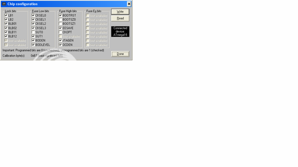
A little about the board's configuration...
I have the clock set to 8Mhz. CKSEL3:0 is set to 0100. SUT1:0 is set to 10. BODLEVEL and BODEN both set to 1 (unprogrammed). So the low fuse is 11100100 = 0xE4.
Bit Bit No. Description Value
BODLEVEL 7 Brown-out Det. trig. level 1 (unprogrammed)
BODEN 6 Brown-out Detector enable 1 (unprogrammed)
SUT1 5 Select start-up time 1 (unprogrammed)
SUT0 4 Select start-up time 0 (programmed)
CKSEL3 3 Select Clock source 0 (programmed)
CKSEL2 2 Select Clock source 1 (unprogrammed)
CKSEL1 1 Select Clock source 0 (programmed)
CKSEL0 0 Select Clock source 0 (programmed)
The high fuse looks like
Bit Bit No. Description Value
OCDEN 7 Enable OCD 1 (unprogrammed)
JTAGEN 6 Enable JTAG 1 (unprogrammed)
SPIEN 5 Enable SPI Downloading 0 (programmed)
CKOPT 4 Oscillator options 1 (unprogrammed)
EESAVE 3 EEPROM memory is preserved 1 (unprogrammed)
BOOTSZ1 2 Select Boot Size 1 (unprogrammed)
BOOTSZ0 1 Select Boot Size 1 (unprogrammed)
BOOTRST 0 Select reset vector 1 (unprogrammed)
11011111 = 0xDF
I may have done something a little wrong, but I'm not sure...
Cheers
The IR function is still not doing as it should. I've tried four remote controllers and a 'scanning' universal controller, but the board refuses to 'see' the controller. I've used both 36kHz and 38kHz versions of IR receiver. Can you help please?
A little about the board's configuration...
I have the clock set to 8Mhz. CKSEL3:0 is set to 0100. SUT1:0 is set to 10. BODLEVEL and BODEN both set to 1 (unprogrammed). So the low fuse is 11100100 = 0xE4.
Bit Bit No. Description Value
BODLEVEL 7 Brown-out Det. trig. level 1 (unprogrammed)
BODEN 6 Brown-out Detector enable 1 (unprogrammed)
SUT1 5 Select start-up time 1 (unprogrammed)
SUT0 4 Select start-up time 0 (programmed)
CKSEL3 3 Select Clock source 0 (programmed)
CKSEL2 2 Select Clock source 1 (unprogrammed)
CKSEL1 1 Select Clock source 0 (programmed)
CKSEL0 0 Select Clock source 0 (programmed)
The high fuse looks like
Bit Bit No. Description Value
OCDEN 7 Enable OCD 1 (unprogrammed)
JTAGEN 6 Enable JTAG 1 (unprogrammed)
SPIEN 5 Enable SPI Downloading 0 (programmed)
CKOPT 4 Oscillator options 1 (unprogrammed)
EESAVE 3 EEPROM memory is preserved 1 (unprogrammed)
BOOTSZ1 2 Select Boot Size 1 (unprogrammed)
BOOTSZ0 1 Select Boot Size 1 (unprogrammed)
BOOTRST 0 Select reset vector 1 (unprogrammed)
11011111 = 0xDF
I may have done something a little wrong, but I'm not sure...
Cheers
Last edited:
chiily,
I can not comment on a firmware which is not made by us. So please try to set your VC using vicol-audio original firmware.
Setting any universal remote should take only few minutes. Just manually scan till the VC power off - do not use auto-scan as this can be faster than VC response.
Regards,
Tibi
I can not comment on a firmware which is not made by us. So please try to set your VC using vicol-audio original firmware.
Setting any universal remote should take only few minutes. Just manually scan till the VC power off - do not use auto-scan as this can be faster than VC response.
Regards,
Tibi
A step closer.
I've found a RC that will turn the VC on/off and select the input. Though the volume control still doesn't work.
Small steps. At least it proves that the IR receiver is working!
I've found a RC that will turn the VC on/off and select the input. Though the volume control still doesn't work.
Small steps. At least it proves that the IR receiver is working!

New DanZup VC boards version 2.1b.
Regards,
Tibi
By the look of it the firmware for your new version should work on the old version. Can you confirm? I can't see much that has changed other than fix a few 'mistakes' on the v1 boards 🙂
Cheers
chiily,
Confirm that new firmware will work on old boards as well.
Beside corrections, new boards will add some minor improvements as well. 🙂
Regards,
Tibi
Confirm that new firmware will work on old boards as well.
Beside corrections, new boards will add some minor improvements as well. 🙂
Regards,
Tibi
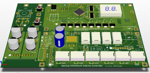
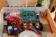
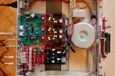
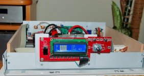
My controller
My version of this volume controller with FarmTech's firmware, connected after a NOS DAC and JBoz like preamp.
The controller worked smoothly from first, just follow the instructions.
...the case is yet to be finished 🙂

My version of this volume controller with FarmTech's firmware, connected after a NOS DAC and JBoz like preamp.
The controller worked smoothly from first, just follow the instructions.
...the case is yet to be finished 🙂
Attachments

Hi
Could I ask how much does it cost for a set of board, including Pre programed Amtel and shipping to Sydney Australia ?
Regards
Could I ask how much does it cost for a set of board, including Pre programed Amtel and shipping to Sydney Australia ?
Regards
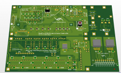
Latest version 2.1b boards are ready for shipping.
Thanks for your patience, in the next two weeks we begin to meet all orders.
Regards,
Tibi
I would like to purchase a balanced LED board set but I saw no way of ordering it on your webshop page. Can you please advise me.
Thanks, Bill
Hello,
Now on the webshop you have following options:
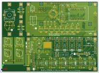
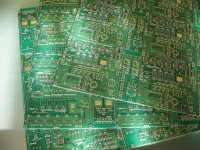
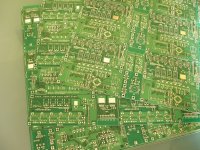
1. Only PCB board - You get the board seen in my previous post
2. PCB with Atmel - You get the board and Atmel microcontroller mounted and programmed
3. Ready mounted - You get the whole volume-controller mounted and tested. All you need is to power (9V/1A trafo) and connect to your pre/power amplifier.
4. Balanced version - You get the balanced volume-controller mounted and tested. All you need is to power (9V/1A trafo) and connect to your pre/power amplifier.
Please do not forget to add shipping at the end of your order.
Regards,
Tibi
Now on the webshop you have following options:
1. Only PCB board - You get the board seen in my previous post
2. PCB with Atmel - You get the board and Atmel microcontroller mounted and programmed
3. Ready mounted - You get the whole volume-controller mounted and tested. All you need is to power (9V/1A trafo) and connect to your pre/power amplifier.
4. Balanced version - You get the balanced volume-controller mounted and tested. All you need is to power (9V/1A trafo) and connect to your pre/power amplifier.
Please do not forget to add shipping at the end of your order.
Regards,
Tibi
Last edited by a moderator:
- Status
- Not open for further replies.
- Home
- Group Buys
- GB for R2R audio volume / input selection pcb