
Markus - I have a set put aside for you now.
I think we are down to the last set of cosmos pots now....
I think we are down to the last set of cosmos pots now....
All cosmos pots are now spoken for, and all PayPal requests have gone out now as well.
5 more packs going out in tomorrow mornings post.....
5 more packs going out in tomorrow mornings post.....
Hi all
The first packs should be arriving in the next few days to a week with their new owners - I hope all arrive safely and quickly.
There are just 3 people left to pay - there is no hurry on this of course, but if you subscribed and have not paid, I thought it a good idea to post here in case it was missed it is very easy for a paypal request to end up in spam.
Shoot me a pm if you want to wait a bit before paying, or if you want to make any changes.
I am excited to see what each of you make of the amp and how you like it.
Fran
Ah great.
In essence all packs have now gone out for this group buy, I am really looking forward to hearing how you get on with the build. Please do add yourself to the thread over in the SS amps forum! https://www.diyaudio.com/community/threads/hiraga-le-monstre-2024.413301/
That way we can all learn from each other as we build.
Fran
Same here, my parts arrivivd yesterday, many thanks Fran and Patrick!
Now I am currious, hope to finalize the build till Christmas.
Now I am currious, hope to finalize the build till Christmas.
Hi all,
I have a had a few queries about setting up the amp - particularly as people are ordering parts.
So first of all, I would say it is really important to read the instructions a few times - I do this with the boards in hand along with the original schematic (see the first post of this thread) to familiarise myself with the boards and options. You cannot skip this step!!
Then when it comes to the current bypass there are two steps to follow:
1. You must determine the bypass current you need - see steps 1-5 on the first page of the instructions for how to do this.
2. Decide what type of bypass you want to do.
The simplest is just a resistor - see picture A on the instruction sheet. Ignore the values you might be able to see in that photo - you will have to determine the correct values through the 5 steps.
Possible, but not recommended - you can use a trim pot, but ultimately this is not as good a solution as fixed resistors. It might be useful though determine the exact value you need.
You can also make a CCS with 2sk208y or 2sk209Y. This is a little more tricky because you have to adjust it in circuit to get the right value. For example, it might be useful to solder a trim pot across the pads (instead of the 2x 0805 resistors in photo C) to get the right value of resistor, and then replace the pot with the fixed resistors.
Someone asked - Rg10 can be 200r or 240r (gate stopper) without issue.
Great to see building underway but please do post questions here - we will all learn from them!
Fran
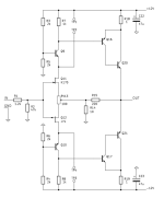
Fran told me that some of you wanted a labelled schematics.
I didn't make one, as it is essentially the same as the original, except for the bypass, for which there are multiple options.
Putting all these options on the schematics is likely to cause lots of confusion, as then some might not bother to read the instructions.
It is MOST IMPORTANT that you take time to read AND understand the instructions before even starting to order things.
If you must have one, I'll make one for you.
But I am still most concerned it creates more confusion than clarity around the CCS bypass.
To understand how it works, refer to the original pdf, and :
www.diyaudio.com/community/threads/hiraga-le-monstre-2024.413301/post-7775591
www.diyaudio.com/community/threads/hiraga-le-monstre-2024.413301/post-7778960
The bypass is placed between TP1&2, and TP3&4.
The values are different between the positive and the negative sides, even if the JFETs are perfectly matched.
You have to follow the instructions.
Patrick
Attachments
Last edited:
Also, for people using TOCOS trimmer (10R), please remember you need to add 2x 43R resistors in series to make up 100R in total.
We tried using a single 100R single-turn trimmer before, and it was way too sensitive to adjust.
This is why we use ourselves ( 43R fixed --10R trim -- 43R fixed ) instead.
If you want to use a single trimmer, you should use a multi-turn one., as suggested in the BoM.
Patrick
We tried using a single 100R single-turn trimmer before, and it was way too sensitive to adjust.
This is why we use ourselves ( 43R fixed --10R trim -- 43R fixed ) instead.
If you want to use a single trimmer, you should use a multi-turn one., as suggested in the BoM.
Patrick
Those who must have the schematics corresponding to our PCB can contact Fran by PM.
He can send that to you as pdf by email. He is very busy, so be patient with him.
It is only for your own use and should not be reposted here or elsewhere.
I cannot emphasis more that you read the instructions and understand how to set the bypass before using the schematics.
For the three bypass options, we chose to use the fixed resistor version in our final build for simplicity.
However, if you wish to be able to adjust bias easily, you can use the trimmer version (on sockets) to start with.
Following the instructions, set DC offset with the TR in the middle, and let it warn up for half an hour.
Then readjust TR9, TR10 to lower bias and retain DC offset without touching the middle TR again.
You can easily measure bias via voltage across the 1R power resistors.
Once done, remove the trimmer and measure the resistance across the appropriate pins.
Then replace with 0805 Susumu thin film (fixed) resistors.
Fine adjust DC with middle TR if necessary.
Looking forward to seeing your own builds,
Patrick
Folks,
The SSP3 speaker protection boards can be built as a mirror pair if you choose to do so. This is only cosmetic of course, but some might find it handy as it allows the input and output to "flow". If you look you will see there is provision for some components to be mounted either side, for example R6 or R6', and the caps can be mounted on the other side so that there is clearance at the heatsink. Totally up to yourselves what you want to do.
Fran
- Home
- Group Buys
- GB for Hiraga Le Monstre 2024