So another couple of angles to consider. Not that I am full of sage building advice -
1. The boards should 'power on' with Toshiba FE JFETs in, and no outputs.
2. The boards should 'power on' with Input/output JFETs in but no attached transformer (did this one experiment quite by accident). LED's at least will light.
3. Hooking up tranformer backwards will cause a short (did that)
4. Not getting the pads from daughter card to transformer, and from female pins to main board all soldered in (especially where we see the the cream colored copper traces) will cause a short.
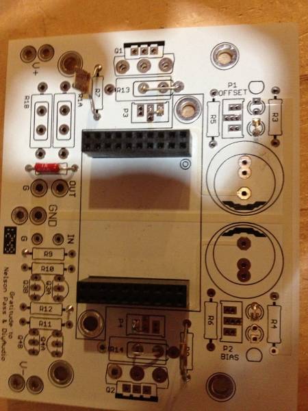
The Cinemags are mounted correctly to DC board (only one way to do that) Letting faces front end. All units the circle on DC faces the caps.
I did all things things building the 4 different protoboards and two production boards I built 🙂 All in the name of troubleshooting
yes, one should try with IRF's (even small ones) first before moving to SemiSouths.
If you go unbuffered, leave the 1K/47K in signal path. I did this without, even with a low R source, and still got some motorboating on speakers.
1. The boards should 'power on' with Toshiba FE JFETs in, and no outputs.
2. The boards should 'power on' with Input/output JFETs in but no attached transformer (did this one experiment quite by accident). LED's at least will light.
3. Hooking up tranformer backwards will cause a short (did that)
4. Not getting the pads from daughter card to transformer, and from female pins to main board all soldered in (especially where we see the the cream colored copper traces) will cause a short.
The Cinemags are mounted correctly to DC board (only one way to do that) Letting faces front end. All units the circle on DC faces the caps.
I did all things things building the 4 different protoboards and two production boards I built 🙂 All in the name of troubleshooting
yes, one should try with IRF's (even small ones) first before moving to SemiSouths.
If you go unbuffered, leave the 1K/47K in signal path. I did this without, even with a low R source, and still got some motorboating on speakers.
Last edited:
Look for the circles to match in direction.
PKI, it looks like your transformers are on backwards on the main board.
The little circle you can see towards the top needs to match the circle on the main board. They face the caps. You front one looks to be heading backwards.
Keep in mind, hooking the transformer to the daughter card the first and second pins on all models are 'keyed' sort of with pins 1 and 2 close together.
But the pins themselves are not keyed, so the circles need to match.
Just to show how cool the boards are:

🙂
PKI, it looks like your transformers are on backwards on the main board.
The little circle you can see towards the top needs to match the circle on the main board. They face the caps. You front one looks to be heading backwards.
Keep in mind, hooking the transformer to the daughter card the first and second pins on all models are 'keyed' sort of with pins 1 and 2 close together.
But the pins themselves are not keyed, so the circles need to match.
Oh, I think I just plug it in wrong. Is this correct?
An externally hosted image should be here but it was not working when we last tested it.
OK took the jfets out and jumpered the input to the xformer input. Is there anything else I need to do for unbuffered?
I can not get the mosfets to bias up now. Running 2 blue LEDs each rail.
Do I really jumper the source resistors? They are 0.5 ohm. I also have the harmonic pots in place. Do those really need to come out and be jumpered?
I can not get the mosfets to bias up now. Running 2 blue LEDs each rail.
Do I really jumper the source resistors? They are 0.5 ohm. I also have the harmonic pots in place. Do those really need to come out and be jumpered?
THe bias net for the output mosfets can be tested without the mosfets in place. IF you are using the IRF fets, yu definitely need the Rs.
I removed the harmonic pots and no effect. I can adjust the offset but for some reason voltage is not getting to the gates.
Might have to yank the MOSFETs out next and see if something fried them when the jfets cooked those 2 resistors.
Might have to yank the MOSFETs out next and see if something fried them when the jfets cooked those 2 resistors.
PLease post pics of boards. IF you pull the pots, you must jumper that position. Pull the mosfets, and test just the bias section. Post pics first as we may be able to spot something. You can test continuity on the board with DMM any questionable location.
Assuming the jumpers are on the pot positions near the source resistors -
Here is a pic from blog with jumpers over P3 and P4. They connect 'to the right' of the Pot.
It may just be that you need to bias the crap out of your IRF's.
Regardless of output FET types (R100 or IRF etc), this unit bias's up from nothing to a lot very fast. Always have the plug ready to pull!
Here is a pic from blog with jumpers over P3 and P4. They connect 'to the right' of the Pot.
It may just be that you need to bias the crap out of your IRF's.
Regardless of output FET types (R100 or IRF etc), this unit bias's up from nothing to a lot very fast. Always have the plug ready to pull!
Last edited:
Yes. I am pulling info together. Ill post the standard kit cost tonight and then add cost of small signal transformers when i get it.
Anyone know where to buy matched GENUINE..2SK170GR and 2SJ74GR?
Or BL ones..
Or maybe they will allso be included in the GB?
Or maybe they will allso be included in the GB?
Why not. Buzz is working on that I am sure. Question is which is more suitable, 4x GR or two BL?
The cost of the parts kit is $63.10. It includes all the components in this schematic. I am using PRP, Caddock, and Elna Silmic II. They are excellent quality for not much money. I will post a link to a GB sheet in next couple of days. I will also look into the the cost of both Jensen and Cinemag transformers and at that as an option. Do not forget about the toroid GB going as well. It is our best chance of getting a quality power transformer at reasonable prices.
Attachments
Buzz, Elna Silmic II 1000uf will not fit the caps space on the pcb, I guess...
They fit mine😀
The cost is for stereo kit.
Last edited:
- Status
- Not open for further replies.
- Home
- Group Buys
- GB for F6 Convertible Clone boards