Hi guys,
I've been messing with the deluxe b1 layout again. (sorry).
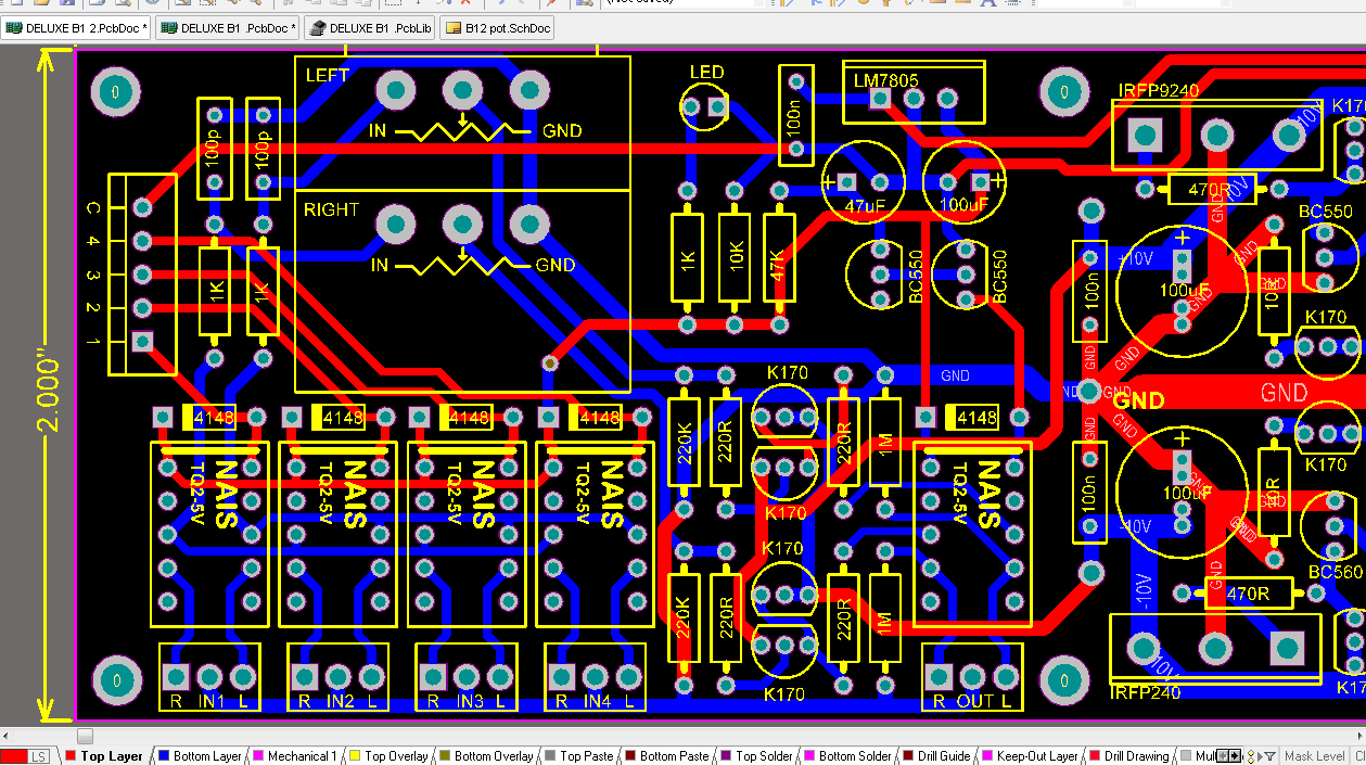
PLease see the layout below..
some changes made:
1. Optional RC filter for RF at the input of the potentiometer ( can easily be jumpered if desired)
2. Move the mute relays on the right side of the Buffer. this keeps the K170 jfets away from the heat of the shunt Fets. this also makes the signal trace from the potentiometer much shorter.
3. update the silkscreen of the pot and relays..
what do you think about this guys?
I've been messing with the deluxe b1 layout again. (sorry).
PLease see the layout below..
some changes made:
1. Optional RC filter for RF at the input of the potentiometer ( can easily be jumpered if desired)
2. Move the mute relays on the right side of the Buffer. this keeps the K170 jfets away from the heat of the shunt Fets. this also makes the signal trace from the potentiometer much shorter.
3. update the silkscreen of the pot and relays..
what do you think about this guys?
Salas said:Hi xaudiox. How near you are for testing prototypes? The numbers in the Wiki have climbed very high. Maybe the pcb maker must give an even better pricing now?
Hi Salas,
I'm still waiting for the nais relays i've ordered from Ebay..they should arrive this week.. I'll ask again for quotation for the pcb.
thanks
Hi xaudiox, it seems that the time has come to call for a design stop. IMO it can't be improved anymore except for very tiny details (maybe) !
Again the PCB is technically better than its predecessor and it also looks better in balance.
On the picture it seems clearance between the ground track and the signal tracks at the upper side of the Alps is very small or is this only at the picture like this ?
Again the PCB is technically better than its predecessor and it also looks better in balance.
On the picture it seems clearance between the ground track and the signal tracks at the upper side of the Alps is very small or is this only at the picture like this ?
it is small.. this is just a quick layout i've done. and will correct the minor details after i see if the members like the the new layout.. thanks for pointing it out..🙂
no more requests from me. go ahead and make those final changes, like the spacing between the potentiometer contacts and ground trace at the top left that jean-paul pointed out, but everything else is just a matter of building the prototypes ... and hopefully finding nothing wrong. i wish i could say that about my latest creation. unfortunately not, i am still debugging off and on three weeks later.
it looks amazing. thank you.
it looks amazing. thank you.
A couple of ideas:
1. you can short the pads for the R in the filter: if you're not using them, you save two solder joint and 10 mm of wire. If you want to include the optional filter, you simply cut the tracks.
2. if L&R tracks are too close or near other possible source of noise, you can "protect" them with a signal gnd track aside going to nowhere.
Cutting of tracks is not as elegant as jumper wires IMO. Just compare the PCB with and without filter. You probably won't hear it having negative side effects and if you do just place a jumper and remove the caps.
The 10 mm of wire and 2 soldering connections won't hurt.
I understand your thinking but in that case the RCA connectors should be on the PCB too. Life is full of compromises....
The 10 mm of wire and 2 soldering connections won't hurt.
I understand your thinking but in that case the RCA connectors should be on the PCB too. Life is full of compromises....
Quick question:
What transformers should I start scrounging for? I have a few with 25V dual secondaries, but murphy being alive and well, I'm sure they won't do for this project?🙄
I have a few smaller 12v ones as well. I guess they're about 20 or 25VA
Fran
What transformers should I start scrounging for? I have a few with 25V dual secondaries, but murphy being alive and well, I'm sure they won't do for this project?🙄
I have a few smaller 12v ones as well. I guess they're about 20 or 25VA
Fran
This is a very impressive effort you guys!
We should give xaudiox an award or something! Good Job!
Mark

We should give xaudiox an award or something! Good Job!
Mark
The pc boards look awesome.
What's the difference between basic and deluxe? I've got myself down for 2 deluxe boards (in the wiki).
Has anyone complied a BOM yet?
What's the difference between basic and deluxe? I've got myself down for 2 deluxe boards (in the wiki).
Has anyone complied a BOM yet?
Basic is two channels and +/- shunt regs on a pcb. You add mechanical input selector and 22k Log pot mounted on chassis, or just the pot for single input.
Deluxe sports what is on basic, plus 4 onboard relay switched inputs, relay mute output power on delay, extra input filter option for less bandwidth and RFI. Also Alps Blue sized onboard pot pads.
In short, basic is the business buffer module, deluxe is a fixed configuration buffer preamp. Both are DC coupled throughout.
I found a nice linear PS with +14V-GND-14V outputs in my junkbox. Also has a 5V supply ideal for the lightspeed I intended using with the B1.
BUT: Can I use this directly into the shunt or am I better off going back to using a transformer to feed it (12V secondaries right?). If I do use it directly in, is the 14-15V it can output enough headroom for the shunt?
Sorry for the newbie question....
Fran
BUT: Can I use this directly into the shunt or am I better off going back to using a transformer to feed it (12V secondaries right?). If I do use it directly in, is the 14-15V it can output enough headroom for the shunt?
Sorry for the newbie question....
Fran
woodturner-fran said:I found a nice linear PS with +14V-GND-14V outputs in my junkbox. Also has a 5V supply ideal for the lightspeed I intended using with the B1.
BUT: Can I use this directly into the shunt or am I better off going back to using a transformer to feed it (12V secondaries right?). If I do use it directly in, is the 14-15V it can output enough headroom for the shunt?
Sorry for the newbie question....
Fran
Found this trafo on your side of the pond. Hope it helps.
woodturner-fran said:I found a nice linear PS with +14V-GND-14V outputs in my junkbox. Also has a 5V supply ideal for the lightspeed I intended using with the B1.
BUT: Can I use this directly into the shunt or am I better off going back to using a transformer to feed it (12V secondaries right?). If I do use it directly in, is the 14-15V it can output enough headroom for the shunt?
Sorry for the newbie question....
Fran
No. Its marginal, plus it adds a whole questionable circuit before the desired circuit.
Thanks guys, appreciate it. I think I might have a couple of 12V transformers knocking about in same said junkbox. Useful for something huh!!? 😉
Following a rule I made for myself a while back.... do the casework first (else it don't get done!)...... the case for this one is coming on nicely. Paint is applied, lacquer is next, wooden front panel is oiled and nearly ready for mounting. Need to pick up some brass to make the knobs next to match my F5.
Looking forward to this build!
Fran
When it come to select a transformer you might want to consider a so called two chamber EI-type of transformer (one chamber for the primary and the second for the secundaries) over a toroid. Otherwise you may at least prefer a (EI or toroid) transformer with a shield between the primary and secondary to diminish capacitive coupling. There have been a few threads about this.
As for the voltages it depends on what you prefer: a standard full bridge with the well known capacitive filter, which implies that the rectified voltage will be about 1.4 times the AC-voltage. Or a so called choke input filter that will result in a 0.9 times the AC-voltage of the secondary. The latter is supposed to give better audible results, but would require a higher secondary voltage and - in this case - two (bulky) chokes.
A third option to obtain the desired DC-voltages is to apply the charge transfer power supply of ec-designs in the Digital section, which would require four secundaries with each an even higher secondary voltage to be set by experimentation.
Your choice. Arjen.
So, a 12v secondary tranformer will give about 17VDC.
Will it be Ok with an EI type 2x12v/10Va or 16Va ?
Will it be Ok with an EI type 2x12v/10Va or 16Va ?
Yes, you can use both but the 16 VA would be somewhat better technically. That having said I have to admit I will be using a 10 VA type myself...
Normal EI types in general are to be preferred (technically) over a toroid because of the broadband character of a toroid. Pollution on the mains will enter the power supply and thus the regs have to do more work. IMO that is their job so they shouldn't complain. FWIW I use toroids without hesitation and accept their drawbacks.
Toroids and especially the bigger variants hum more easily than normal transformers when there is a slight DC component because of pollution/distortion on the mains.
But toroids are smaller, use less power and are easier to mount etc. so it depends on what you prefer.
The nais relays arrived yesterday, i'm finalizing the layout of both boards and will do the prototypes today, hopefully tonight i can show some scope screen shots and some measurements...thanks for your patients.
- Home
- Group Buys
- GB for DC coupled B1 buffer with shunt PSUs