I thought about the footprint for the Alps pot on the pcb for some time
and decided not to like it too much. Two reasons for this:
1) I would not want to use the Alps pot anyway since I consider it mediocre.
This buffer certainly deserves a better pot (or a stepped attenuator).
2) Even if you decide to use the Alps pot on its footprint, you are extremely
limited in designing or finding a proper casing. The pcb is very long but not wide
and the pot sits at one end of it. So the case needs to be at least 7" wide inside,
probably even more because of the cabling.
I really think that you loose more than you win with the footprint for the pot.
Having a slightly smaller pcb and an external front mounted pot seems to be
a better solution to me...
I think this was Holger's objection, too...
FWIW,
I think michi124 is on the button on this one. Those alps pots are mediocre at best, despite all the hype about them. A cheap built stepped attenuator offa ebay for $20 beats them hands down.
Personally I hope to use a lightspeed attenuator for this B1, but if that doesn't wok out then I have a stepped pot ready to go here.
Its just the footprint behind the alps is huge.
However, may I add that I appreciate that to change the design is extra work and I will take gladly whatever I receive!
Fran
woodturner-fran said:
Personally I hope to use a lightspeed attenuator for this B1
+1
Thanks for the replies guys,
as for the concern, yeah there are certainly very good pot aside from alps, i too have a dale stepped attenuator that i'm planning to use with the B1.
Even if i remove the alps on the pcb, due to the added relay's, the pcb size will still stay almost the same size or abit smaller. You can just use the Basic B1 if you have limited case space and dont want the added relays.
I'm also building one Deluxe B1 for a friend with alp pot.. The pcb will be place at the back, near the rca jacks and use extension rod for the alps pot.
like i said before, i'm always ready to change any part of the layout if its what the majority of the members want and makes the whole design better.. 🙂
as for an update, sorry i havent started with the prototype of both versions, been busy with work and got throat infections this past week.. but i'm feeling better now..
thanks guys
Not everybody is into stepped attenuators and implementing them or another type/brand potentiometer while the pads are already there should be enough, isn't it ? For those that wish everything external there is the standard PCB. External stepped attenuator and source selector and off you go 😉
The Deluxe PCB should be mounted at the rear of any case where it fits in width. Just use an extension shaft to the potentiometer and you will have very short wiring ( if at all ) to the RCA connectors. That seems to be the way to work with this PCB.
edit: Sorry xaudiox, I was posting the same thoughts at about the same time you were posting it seems.
jean-paul said:Not everybody is into stepped attenuators and implementing them while the pads are already there should be enough, isn't it ? For those that wish everything external there is the standard PCB. External stepped attenuator and source selector and off you go.
The Deluxe PCB should be mounted at the rear of any case where it fits in width. Just use an extension shaft to the potentiometer and you will have very short wiring ( if at all ) to the RCA connectors. That seems to be the way to work with this PCB.
edit: Sorry xaudiox, I was posting the same thoughts at the time you were posting it seems.
++
This is a sweet all in one solution board. I am building one and am planning on using a shaft extension. I will be using the basic for my other project where I have other plans for selector and attenuator.
I would suggest to remove the pot
Make the basic and deluxe into one board, with beakable relay board
Very few will need the supply board only, and whether breakable supply board should be granted is up to you
If its better when not that would be my suggestion
Then we all would order the same
Cost might be even lower
It was suggested by several members before, but at a time when xaudiox was away, and didnt read all that was posted, in his own words
almost 50 % of the requirements seem supply only board ( basic Board is Supply board ) However ordering one single board is good idea. This would make this project move along quickly in to getting the boards on hand
I vote fo breakable! 🙁and whether breakable supply board should be granted is up to you
And if you make it one board,even make the relay board breakable so I (we) can use the buffer and PSU only..
Seems I made a poor evaluation on the need for supply board only
Point is that last time we talked about a single board with breakable sections this seemed popular
Fact is, what is there not to like about it, when everyone get what they want
Unfortunately xaudiox was away and didnt know about it
And I agree with those who dont like the onboard alps pot
Point is that last time we talked about a single board with breakable sections this seemed popular
Fact is, what is there not to like about it, when everyone get what they want
Unfortunately xaudiox was away and didnt know about it
And I agree with those who dont like the onboard alps pot
Exact.😉Fact is, what is there not to like about it, when everyone get what they want
Onboard alps pot:
If its not holding back the design or affecting the layout, then anyone who wants to can just wire in their own choice (me included).
I'd only go to the bother of changing it if it made the layout simpler/easier better etc etc.
But to those who are thinking of using one.... honestly, they aren't that great!😉
Again, sincere thanks to xaudiox and others for your efforts on this. You do this sort of stuff that I know I could never attempt and allow the likes of me to build some amazing gear
Fran
Keep in mind that the 220k input resistor which is there to safeguard against dodgy pot DC incidents and MUST be used, by effectively shunting the wiper to ground will change the subjective pot quality and its channel matching for the better too.
'' Slightly OT, but... Post #517
... I've tried this with a QC24 today (basically a pot followed by a 6111WA gain stage), and it seems to work in that context, too. The slight midrange dip, that the pot introduced, went, and a touch of harshness with it. I used two 1M Dale CFM55s in parallel for each channel, the pot is a 47K black Alps (allegedly NOS, but I'm not sure about that).
Excellent hint, thanks Salas.
Best,
Oliver''
Original discussion
Ryssen said:
I vote fo breakable! 🙁
And if you make it one board,even make the relay board breakable so I (we) can use the buffer and PSU only..
agreed, I for one don't want the relay or the fancy pots, and will want a few for PSU only.
I vote for one 'breakable' board.
woodturner-fran said:mmm, missed that completely salas - that may make a large difference!
Fran
Not large, but better is better. This DC & Shunts B1 is so clean and noiseless you gonna focus on things sooner or later. And if you gonna focus, its a party spoiler. Keep a typical popular pot size in the layout and if using chassis mounted stepped or a light coupled attn circuit or carbon TKD or whatever, just wire it to the respective pads. No sweat.
i agree with salas and jean paul.. anyone can just wire their desired pot onto the pads of the alps pot.😀
i think we should retain 2 versions instead of one big board with all the options included..
@salas. what do you think of adding RC circuit at the input of the pot? i believe the b1 have bandwidth of more than 10mhz, the rc filter can keep the RF away.. Let's say 1 kOhm and 100 pF polystyrene or MKP = 150 kHz -3 dB.. what do you think? this is just another option that can easily be jumpered if you dont feel like it..
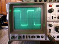
The input interconnects will have 100-150pF easily, add average source impedance to the 220R stopper and its already been taken care of. Haven't seen any oscillation on 100kHz squarewaves. If there was an issue, Nelson Pass would include such a filter in the original B1. Don't bother IMHO. 1k series, is audible. Adds too much source impedance. The dynamics are softened, and the resistor quality becomes more obvious. That is why I got down to minimum 220R stoppers.
100kHz close up.
100kHz close up.
Attachments
- Home
- Group Buys
- GB for DC coupled B1 buffer with shunt PSUs