jean-paul said:Maybe when xaudiox still is working on the layout he could add pads for using MUR diodes ( in TO220 case ) as well. Could you add this possibility xaudiox ?.
Hi, I did try that but with the current spacing and orientation of the diodes, there's not enough space between the diodes. the 4th and 5th diodes, their tab are facing each other, which is my main concern..
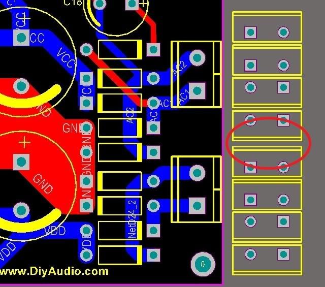
The 4th and 5th diode could be isolated with a piece of dielectric material and stuck toghether with a nylon screw or a shrinkable sleeve.
I lost track of the origin of this latest round of modifications. What triggered the desire for this change?
Is it still related to the mute delay ... or did it just spin off from that?
Is it still related to the mute delay ... or did it just spin off from that?
Don't panic.😀 Nothing serious. It is about providing for 5V and 12V muting relay operation. Its essentially ready.😉
xaudiox said:
Hi, I did try that but with the current spacing and orientation of the diodes, there's not enough space between the diodes. the 4th and 5th diodes, their tab are facing each other, which is my main concern..
Awkward indeed. Please do not change this as it is a potentially unsafe situation.
grufti said:I lost track of the origin of this latest round of modifications. What triggered the desire for this change?
Is it still related to the mute delay ... or did it just spin off from that?
post #406.
Forgot to mention, that if with a 2X12V trafo and ''enthusiatic Leds'' (seems that with most Leds available, shooting over 10V ref is common), you can use 4 Leds instead of 5 in each row and stay below 10V (you jumper the 5th). Also don't forget to match the Led strings. We are looking for 1.7V to 1.8V average green or yellow or red.
basic b1 working...
hi,
i just finished the protoype for the Basic B1. it works like a charm..
just like what Salas said.. the led string need to be matched.. i didnt match mine since i only have exact number of leds.. 😀
shunt output = + 11.44V and -10.60V
even with the current voltage supply.. the DC offset is about 3-6mV only.
i monitor the dc offset while i turn off the b1.. the dc offset climbs to 400mV after power off..
so it really important to have a mute relay at the output of the B1..
heres some photos..
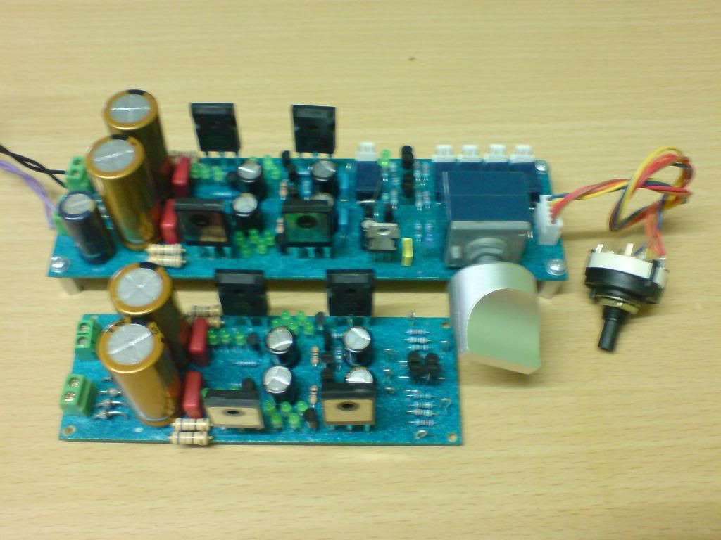
enjoy..
😀
hi,
i just finished the protoype for the Basic B1. it works like a charm..
just like what Salas said.. the led string need to be matched.. i didnt match mine since i only have exact number of leds.. 😀
shunt output = + 11.44V and -10.60V
even with the current voltage supply.. the DC offset is about 3-6mV only.
i monitor the dc offset while i turn off the b1.. the dc offset climbs to 400mV after power off..
so it really important to have a mute relay at the output of the B1..
heres some photos..
enjoy..
😀
Great! I actually have an output relay in my basic for that reason, so to avoid anything untoward, but Crt did not monitor or did not mention such power off momentary climb when he did the original basic. Maybe after a better +/- reg match it jumps lower? You will see after you will have more Leds. Also, for how long this jump stays?
Salas said:Also, for how long this jump stays?
after power off. from 3mV to 400mV+ in 15secs then drop slowly.. i'm using 3300uf for the main caps..
Don't think about it. Add an output relay as I use. Maybe Crt had all his amps C input and did not notice any woofers going out and sucked back slowly. We will never know if someone will hook it up to a DC input amp and turn off the Basic DC B1 first. The Wiki has many many board requests, and that means many will work out there for many years in different hands.
Also we found an elegant solution about using either 5V relay sets or 12V relay sets with the original delay circuit and no heat on the 3 pin reg. Wanna tell them how?
P.S. If we put the delay circuit audio B1 outer side, anybody with a C input amp can leave it unpopulated if wants to avoid more contacts, and anybody wanting it only for shunts can have his cutting line still.😉
Hi, the muting relay is in the signal path at the moment. Shorting the output to ground keeps the relay out of the signal path. There will be a current path of max. 10 V over the 220 Ohm resistor and a K170 at the moment of muting at power on/off.
What do you think about that ?
What do you think about that ?
shorting the output to signal ground sounds far better.
If the power amp powers off at the same time and relies on a DC servo to correct offset errors then that pre-amp output offset could damage speakers if the power amp passes the DC during power down.
If the power amp powers off at the same time and relies on a DC servo to correct offset errors then that pre-amp output offset could damage speakers if the power amp passes the DC during power down.
Looks great.
I am reading all the comments thus far..
Unsure of a few things.
Will the deluxe be immune to DC Offset problem at turnoff?
Are we planning on a tweak for the Basic to stop this problem?
I will have to look at matching LED's, or diodes. This sounds like the making of a cookbook!
I am reading all the comments thus far..
Unsure of a few things.
Will the deluxe be immune to DC Offset problem at turnoff?
Are we planning on a tweak for the Basic to stop this problem?
I will have to look at matching LED's, or diodes. This sounds like the making of a cookbook!
1. Yes.
2. Yes. Delay output relay there too. Releases instantly after off.
3. One 9V battery, one 1k resistor on +, led from 1k to -, measure Vdrop across led, put em on a piece of paper, note Vdrop under each one, make two comparable VdropTotal strings.
There are some DMMs that measure Vdrop of diode, not only showing if it is working. If having such, no above mini rig is needed.
Michi124 said:Should all relays be 12V or just the mute relay?
We put in there a 1W resistor that feeds 2 relays at a time (one for mute, 1 for selected input). It drops voltage across it so to keep the relay coils at 5V if having a 5V set of relays. But the delay circuit still has 12V so to work as originally planned and no large drop across the 3 pin reg. Using 7812. Keeps its heat at bay. If someone finds say on Ebay 12V relay set pin compatible versions to buy, uses a jumper instead of the relay feed series resistor and has 12V for those.
- Home
- Group Buys
- GB for DC coupled B1 buffer with shunt PSUs