One word of caution -- if you're using the trimmer pots from the BOM, I believe their screw is on the opposite side of where it is on the silkscreen. In that case, make sure to drill the hole in the right spot.
Ripple on half-wave rectified ±65V supplies
This may have been discussed already but if it was I missed it.
The schematic for the EL84 amp has nominal ±65V derived from half-wave rectifiers connected to the mains transformer 50VAC secondary.
My simulation says that ~4mA is drawn from an ideal +65V supply and ~9mA from than ideal -65V supply.
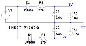
Plugging those currents into a simulation I get 0.2Vpp ripple on the +65V supply with a mean of ~60.74V and 0.4Vpp of ripple on the -65V supply with a mean of -54.3V.
I tried putting that information in my amp simulation with
PULSE(60.64 60.84 0 3ms 17ms 0 20ms 100)
and
PULSE(54.5 54.1 0 16ms 4ms 0 20ms 100)
but all I get out of the simulation is ~120uV of ripple with no signal so I’ll have to go back over the tutorial for adding ripple to power supplies. I can look at the ripple at points within the schematic but I’m not sure the waveforms are trustworthy.
Isn’t the constant current source on the input differential pair sensitive to noise on the negative supply?
How about ripple on the bias and negative rail of the source follower CCSs?
Thanks.
This may have been discussed already but if it was I missed it.
The schematic for the EL84 amp has nominal ±65V derived from half-wave rectifiers connected to the mains transformer 50VAC secondary.
My simulation says that ~4mA is drawn from an ideal +65V supply and ~9mA from than ideal -65V supply.
Plugging those currents into a simulation I get 0.2Vpp ripple on the +65V supply with a mean of ~60.74V and 0.4Vpp of ripple on the -65V supply with a mean of -54.3V.
I tried putting that information in my amp simulation with
PULSE(60.64 60.84 0 3ms 17ms 0 20ms 100)
and
PULSE(54.5 54.1 0 16ms 4ms 0 20ms 100)
but all I get out of the simulation is ~120uV of ripple with no signal so I’ll have to go back over the tutorial for adding ripple to power supplies. I can look at the ripple at points within the schematic but I’m not sure the waveforms are trustworthy.
Isn’t the constant current source on the input differential pair sensitive to noise on the negative supply?
How about ripple on the bias and negative rail of the source follower CCSs?
Thanks.
Attachments
50Vac means around 35Vdc, not 65.
CCS have high impedance so high rejection to noise.
You only need 1.2 mA more on the negative rail (PI's current)
I guess you have overdone something in your simulation, and ripple is way better.
CCS have high impedance so high rejection to noise.
You only need 1.2 mA more on the negative rail (PI's current)
I guess you have overdone something in your simulation, and ripple is way better.
Ripple on half-wave rectified ±65V supplies
I’ve now tested one of my EL84 PCBs. My measurements are very close to the simulation results in my original post.
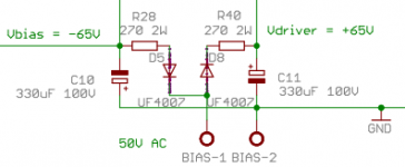
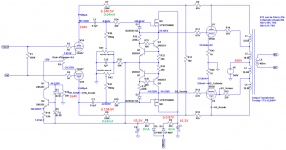
The first image shows the schematic with my measured voltages and currents. HT is 340V regulated.
The second image shows the positive and negative rails derived from the 60VAC bias supply.
As predicted by LTSpice:
Interestingly, there’s no ripple on the output transformer secondary. There must be some cancellation going on in the output stage.
I need to do some frequency and noise measurements on the desktop computer with the fancy sound card but my breadboard power supplies aren’t really moveable to my study.
Anyway, in my final build I’ll regulate the bias-derived supplies down to ±35V.
This may have been discussed already but if it was I missed it.
The schematic for the EL84 amp has nominal ±65V derived from half-wave rectifiers connected to the mains transformer 50VAC secondary.
My simulation says that ~4mA is drawn from an ideal +65V supply and ~9mA from than ideal -65V supply.
Plugging those currents into a simulation I get 0.2Vpp ripple on the +65V supply with a mean of ~60.74V and 0.4Vpp of ripple on the -65V supply with a mean of -54.3V.
Isn’t the constant current source on the input differential pair sensitive to noise on the negative supply?
How about ripple on the bias and negative rail of the source follower CCSs?
Thanks.
I’ve now tested one of my EL84 PCBs. My measurements are very close to the simulation results in my original post.
The first image shows the schematic with my measured voltages and currents. HT is 340V regulated.
The second image shows the positive and negative rails derived from the 60VAC bias supply.
As predicted by LTSpice:
- The voltages are -55.5V and +61.2V.
- Positive rail ripple is ~200mVpp and negative rail ripple is ~400mVpp.
- Positive rail current draw is 4mA and negative rail current draw is 9mA
Interestingly, there’s no ripple on the output transformer secondary. There must be some cancellation going on in the output stage.
I need to do some frequency and noise measurements on the desktop computer with the fancy sound card but my breadboard power supplies aren’t really moveable to my study.
Anyway, in my final build I’ll regulate the bias-derived supplies down to ±35V.
Attachments
Yes, the B+ ripple is common mode. They cancel out in the output transformer as long as the two tubes conduct the same.
-Chris
-Chris
dch53,
Very interesting and congratulations with you close simulation and real-world results! Hope you will enjoy the sound of Baby Huey music.
May I suggest that you request a move (by an Admin) of the previous four posts to the “EL84 Amp - Baby Huey” thread where this information may be more visible and useful to other builders.
Hi Francois,
I'm not sure the posts should be moved. The half-wave rectified supplies are a feature of the design and PCBs in this group-buy thread.
Dave.
I'm not sure the posts should be moved. The half-wave rectified supplies are a feature of the design and PCBs in this group-buy thread.
Dave.
Yes, the B+ ripple is common mode. They cancel out in the output transformer as long as the two tubes conduct the same.
-Chris
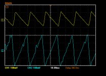
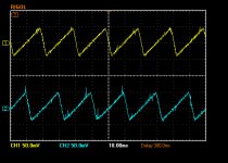
Thanks Chris. The noise is common mode on the output tube grids rather than the B+. It is generated by the preceding LTP because of the half-wave rectification and filtering of the -65V supply on the LTP CCS.
Here's a screenshot of the LTP anodes and A-B showing the perfect cancellation of the noise induced by the noisy supply.
The second image shows the ±65V supplies again.
Dave.
Attachments


Hi Dave,
Having said that, a cleaner supply will allow it to perform better. Especially if the sharp sawtooth were to be filtered to be more of a low frequency sine wave.
-Chris
Having said that, a cleaner supply will allow it to perform better. Especially if the sharp sawtooth were to be filtered to be more of a low frequency sine wave.
-Chris

I have BOM for Mk2, and I see some values are in red. Why?
Is it necessary to use 500V capacitors, since I can source only 450V in my country, and shipping from Mouser and similar services is too high?
R13 in PS is 274k. Why so precise, I suppose any resistor of the similar value can be used there to discharge capacitors???
Is it necessary to use 500V capacitors, since I can source only 450V in my country, and shipping from Mouser and similar services is too high?
R13 in PS is 274k. Why so precise, I suppose any resistor of the similar value can be used there to discharge capacitors???
I've followed the Baby Hueys for years now and want to build another again. Has the EL84 or EL34 Huey boards ever been released in the public domain in either Gerber files or Eagle (if that is what software was used to create them)?
if there are enough requirements for boards, I can produce again..
out of respect for marc, bandol83, I wont release them in public domain
out of respect for marc, bandol83, I wont release them in public domain
It will help if you provide specific information. What BOM (power supply or amp) and what is the date on your BOM - December 23, 2018? Are you talking about the capacitors in orange (C5-7)? Or the PSU BOM dated September 23, 2019 (C3 & 10)? For which output tubes are you building, and what high voltage supply (B+) are you planning to use? That determines the answer to your question.I have BOM for Mk2, and I see some values are in red. Why?
Is it necessary to use 500V capacitors, since I can source only 450V in my country, and shipping from Mouser and similar services is too high?
R13 in PS is 274k. Why so precise, I suppose any resistor of the similar value can be used there to discharge capacitors???
Anyway, we must use capacitors that are capable of your B+ voltages. Good luck with your build. Regarding PSU R13 you are correct, Marc picked a specific value for it, but anything close will be fine.
Last edited:
I would like to purchase a pair of BH el-84 PCBsif there are enough requirements for boards, I can produce again..
out of respect for marc, bandol83, I wont release them in public domain
Steve
- Home
- Group Buys
- GB for Baby Huey PCB