There are no lines to or from the serial connections, and for the selction off the filter I use the J 10 serial RX/TX.
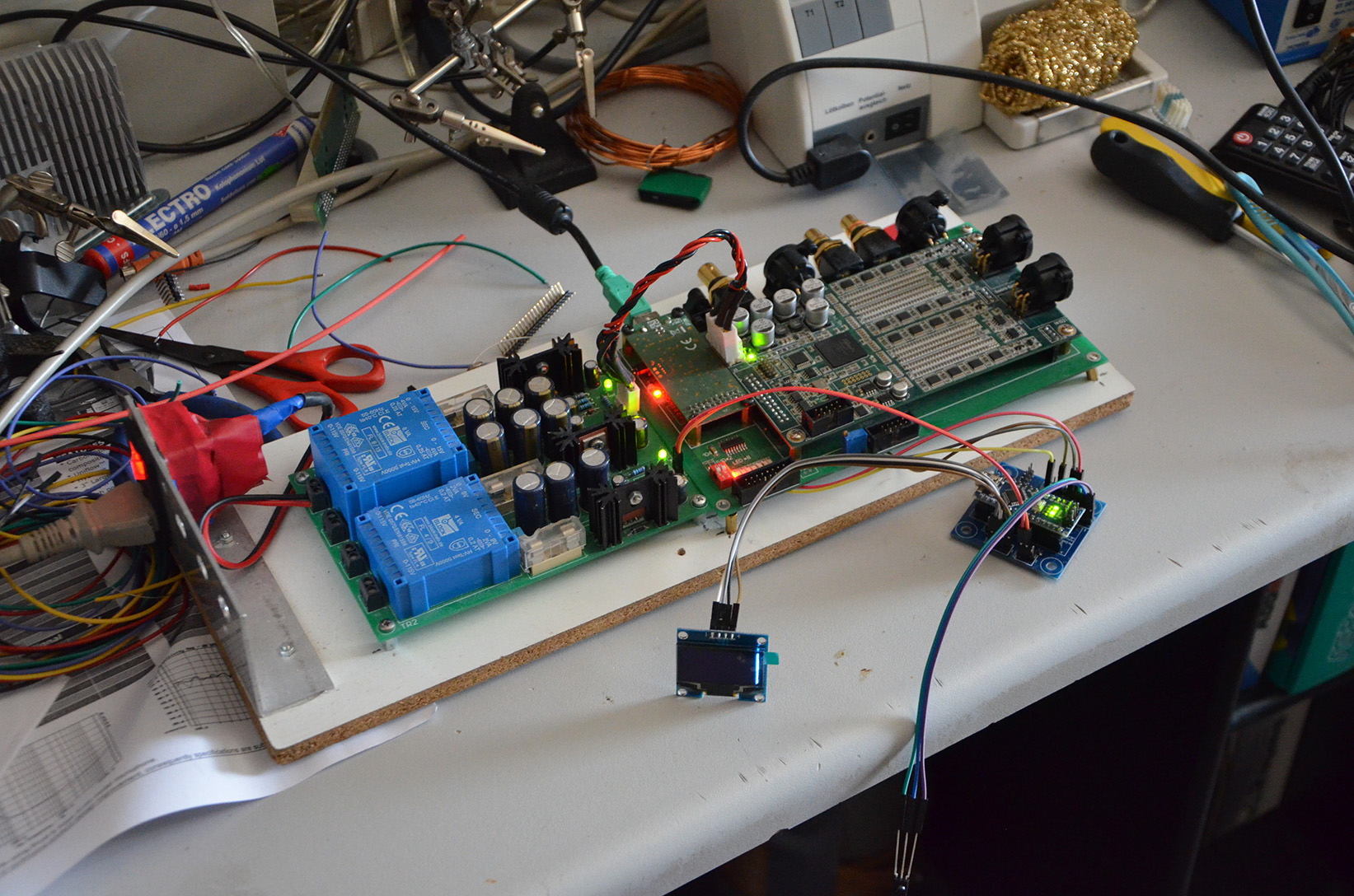
Here a image off the board before the soldering/montage.

Here a image off the board before the soldering/montage.
OK, so these pins are not connected to anything. Good.
How do you know that you are not getting a serial connection?
Have you built the Ardam, loaded the code, connected it to the dam, powered it on, sent it the power-on command from the remote, and nothing happened?
How do you know that you are not getting a serial connection?
Have you built the Ardam, loaded the code, connected it to the dam, powered it on, sent it the power-on command from the remote, and nothing happened?
Until now the connection off 2 wires to the ISOL_SERIAL are not conneted, and the POWER ON command is not given.
There is no reaction, is it RC5 protocol?
Do I need a Apple remote?
There is no reaction, is it RC5 protocol?
Do I need a Apple remote?
The IR library that I am using is this one: Arduino IRremote
It supports a large number of IR protocols.
Take a look at p.4 of the Build Guide, in the Remote Control section.
After picking a remote control (you can use an old one that you have or an Apple remote) you need to determine the IR codes that it uses and insert them into the code. The build guide gives instructions on how to do it.
Because of the isolator issue with the serial port, it's best to do the procedure with the Nano off the board, with only the IR receiver connected.
First chance I get I'll do a version of the code that is by deault powered on, so you'll know if your Ardam works without first having to do the IR configuration.
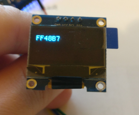
I wrote a small program that helps with determining the compatibility of IR remotes with the library that I am using. When you load the code into your Arduino it will display the detected IR code on the OLED and through the serial port.
More details in the updated Project's Page and Build Guide (v1.1): ArDAM1021 Lite Project | Dimdim's Blog
More details in the updated Project's Page and Build Guide (v1.1): ArDAM1021 Lite Project | Dimdim's Blog
Attachments

My first experiment with the Arduino!
- plug in the (original) Arduino - it was recognized at COM6
- install IDE
- download and install 2 libraries
- download the Ardamlite sketch
- open the Ardamlite and let compile
Compiled and loaded on the Nano, but some warnings (below). Should I worry?
C:\Program Files (x86)\Arduino\Programs\ArDAM_Lite_v0.92\ArDAM_Lite_v0.92.ino: In function 'void loop()':
C:\Program Files (x86)\Arduino\Programs\ArDAM_Lite_v0.92\ArDAM_Lite_v0.92.ino:401:25: warning: overflow in implicit constant conversion [-Woverflow]
prev_result = VOLUP_CODE;
^
C:\Program Files (x86)\Arduino\Programs\ArDAM_Lite_v0.92\ArDAM_Lite_v0.92.ino:413:25: warning: overflow in implicit constant conversion [-Woverflow]
prev_result = VOLDOWN_CODE;
^
C:\Program Files (x86)\Arduino\Programs\ArDAM_Lite_v0.92\ArDAM_Lite_v0.92.ino:419:7: warning: overflow in implicit constant conversion [-Woverflow]
case VOLUP_CODE:
^
C:\Program Files (x86)\Arduino\Programs\ArDAM_Lite_v0.92\ArDAM_Lite_v0.92.ino:431:7: warning: overflow in implicit constant conversion [-Woverflow]
case VOLDOWN_CODE:
^
Programmers only worry about errors, not warnings. 😛
But seriously, I don't remember if I'm getting these errors in my IDE. I'll check first chance I get.
But if the code runs the way it should, I woulndn't worry.
But seriously, I don't remember if I'm getting these errors in my IDE. I'll check first chance I get.
But if the code runs the way it should, I woulndn't worry.
Hi Dimitris,
Thanks for the fast reply!
I just started with the project, still have to prepare the board and connect to the DAM1021.
But another two questions, probably more will pop-up along the way 🙂
- To test the IR codes you wrote the little SW which requires the IR sensor and OLED display to be connected to the Arduino, but this should not be plugged in your board - so plug the IR and OLED straight to the Arduino pins? I do have two of your boards, I could make one with headers for the IR and OLED, but without the serial isolator chip...
- I got this 1.3" 1.3" IIC I2C SPI Serial 128X64 OLED LCD Display Module For Arduino Blue 3.3V/5V | eBay . Which line should I activate - or just keep the 0.96" activ? The driver chip of my oled is SSD1106
U8GLIB_SSD1306_128X64 u8g(U8G_I2C_OPT_NO_ACK); // 0.96" OLED Display using I2C which does not send ACK
//U8GLIB_SH1106_128X64 u8g(U8G_I2C_OPT_NONE); // I2C / TWI
//U8GLIB_SH1106_128X64 u8g(U8G_I2C_OPT_DEV_0|U8G_I2C_OPT_FAST); // Dev 0, Fast I2C / TWI
//U8GLIB_SH1106_128X64 u8g(U8G_I2C_OPT_NO_ACK); // Display which does not send ACK
//U8GLIB_NHD31OLED_2X_GR u8g(3, 21, 22); // SPI Com: SCK = 13, MOSI = 11, CS = 10, A0 = 9
- Yes, you only need to just plug the IR receiver to the Arduino, you don't even need to connect the OLED since you can see the IR codes in your IDE's serial port monitor.
- For the 1.3" OLED you need to comment out the first line and remove the // from this line:
U8GLIB_SH1106_128X64 u8g(U8G_I2C_OPT_NO_ACK); // Display which does not send ACK
- For the 1.3" OLED you need to comment out the first line and remove the // from this line:
U8GLIB_SH1106_128X64 u8g(U8G_I2C_OPT_NO_ACK); // Display which does not send ACK
Hi Dimdim,
Yesterday I resumed working on the ArDam Lite, and got stuck, again 🙂
I used the DAM1021 with I2S connection, fed from a Raspberry. In that configuration, I feed the 3 I2S lines, ground and 3.3V supply from the Raspberry to the DAM – the DAM needs an external 3.3V on ISO +3.3V Pin (because the DAM has an isolator chip for I2S on it?!) – (page 8 of the DAM user manual).
http://www.soekris.dk/download/dam1021/dam1021 user manual 20151005.pdf
According to your instructions, I should connect Pin 6 (of the ArDam Lite Serial header) to Vcc (connect to ISO +3.3V at the DAM’s J3). Pin 6 is connected to Pin 16 of the Serial isolator Chip, and should feed this with 3.3V. But from the above that ISO +3.3V is not a power source.
What am I doing wrong? I would like to keep the Raspberry I2S as source.
Many thanks! Erik
Hi there Erik, you are doing nothing wrong.
The ArDAM's manual says to connect "Pin 6 (of the ArDam Lite Serial header) to Vcc (connect to ISO +3.3V at the DAM’s J3)" assuming that you already have this pin (ISO +3.3V) connected to a suitable power source (in your case, the 3.3V coming from the RPi).
So the "ISO +3.3V" pin should be connected to both your RPi as well as to Pin 6 on the ArDAM.
Many thanks for the fast reply!
actually I thought this would be the case, but typed a bit fast to fast this morning. Great, I will try it next week.
Another question: I have a DAM1021 v1 on which I didnt do any mod or SW upgrade yet, but it is already in circuit and I would like to test the ArDam Lite before doing FW upgrades. Will the ArDam work with the v1?
I also have a v4, but it is still packed 🙂
I don't think that the changes between the first and the second firmware are big enough to cause the controller to not work. You should be ok.
Hi Dimitris
so moved on with the ArDam in the weekend. I changed the IR codes, loaded the Sketch and indeed, it receives the codes, changes volume and so on.
Moved on and connected to the DAM: 3.3V to pin 6, Gnd at pin 1, both Tx and Rx. The DAM is fed I2S from the raspberry. Playing music (moode) the DAM locks, plays nicely, but changing volume at the ArDam doesn't do anything on the DAM.
So, troubleshooting 🙂
First thing I noticed is that I connected Tx and Rx the wrong way around: Tx to Tx and Rx to Rx - so I corrected that. I don't think connecting those wrong can destroy anything?
Than I noticed that when sending commands, Tx led doesn't lit up. I looked at your video, and when you change volume, there is a flickering LED, which must be Tx? So serial not working? I searched on the inet, and found some comments that the Tx LED will only blink when the USB-Serial is active, that is when the serial monitor in the Arduino IDE is active. But why does it flicker on your video? Is it the Nano's "version"?
Well, checking with the serial monitor I am indeed getting the desired signals: V-xx, F5, etc.
I think I could check if there is anything at all at the serial isolated side by separating it from the DAM, feeding it with (isolated) 5V and connecting it to a RS232 port and reading this out with Putty?
Thanks!
Erik
For starters, don't worry about connecting TX & RX the wrong way, you haven't damaged anything.
If the TX/RX LEDs don't light on your Nano there is something going on there.
I don't remember any case of the LEDs lighting having anything to do with the USB port being active or not, but do try things with the USB port disconnected. Also try powering on first the DAM, then the Arduino, and the opposite.
We'll figure it out eventually..
Hi Dimitris,
Thanks again for the reply! The info on Tx LED being only active in USB mode is here:
usb - Arduino won't send serial data if connected with external power supply - Arduino Stack Exchange
But on your Arduino the Tx is indeed flickering when changing volume?
I have indeed powered it from an external 5V supply, so no USB. I will also try different powering on sequences.
Cheers, Erik
I just had a look at the original Nano's schematic and you're right! The LEDs are connected to the USB-to-serial IC.
It appears that my Nano, being a knockoff, uses the CH340 chip and in that case the designer has connected the LEDs directly to the serial lines, before the CH340 chip. That is why I get lights and you don't.
But that shouldn't keep your serial port from functioning.
It appears that my Nano, being a knockoff, uses the CH340 chip and in that case the designer has connected the LEDs directly to the serial lines, before the CH340 chip. That is why I get lights and you don't.
But that shouldn't keep your serial port from functioning.
Hi Dimitris,
That makes things clearer. I would indeed think that as soon as I disconnect the USB plug, the Serial signal would be directed to the respective pins on the Nano.
I tried different power up sequences, but that didnt work either. I do have a knockoff Nano as well, a second ArDam lite PCB, two of the serial chips, so can put a second together.
This morning I have also been reading about Putty, maybe I should tap some signals and to see how far the serial signal is coming?
Cheers, Erik
- Home
- Group Buys
- GB for ArDAM Lite bare PCBs