my parcel arrived at the temporary storage yesterday. Can't wait to pick it up in the next days.
Markus
Markus
If you use Vero boards for mains voltage, make sure you insulate them with multiple layers of PCB PU spray.
They dry much better (quicker and more thorough) if you bake them at 70°C for half an hour or so.
At least that is what I would do.
Patrick
They dry much better (quicker and more thorough) if you bake them at 70°C for half an hour or so.
At least that is what I would do.
Patrick
Thanks for the tip. I was planning to cover the vero board parts with mains voltage with a sheet of plastic.
Me too, this whole thing is amazing Carlos, thank you!
I am literally thinking about putting some veneer on the box and using it to hold a LiFePO4 battery supply, and have the amp will sit on that. I'm justifying the battery purchase as a solar energy storage/backup/secondary use... For power outages.. (class A during a power outage?) 🙂
I am literally thinking about putting some veneer on the box and using it to hold a LiFePO4 battery supply, and have the amp will sit on that. I'm justifying the battery purchase as a solar energy storage/backup/secondary use... For power outages.. (class A during a power outage?) 🙂
Ok so almost all delivered.
The are 2 minor issues discovered by Morde, not serious, one has to do with transistor screw holes in the front panel, and the other has to do with mid extender in the small heatsinks for the cap-multiplier.
Both already have solutions, so i will post details on monday .
get your soldering irons hot....🙂
The first one was apparently XEN's mistake, though I could not understand.
We have made 50 of these cases, so there should have been no more drawing errors.
Our apologies to CeeVee.
We'll see how much the work around costs.
In any case you should not be the one to absorb all the costs.
The front panel anodising issue already cost you a small fortune .........
🙁
Patrick
We have made 50 of these cases, so there should have been no more drawing errors.
Our apologies to CeeVee.
We'll see how much the work around costs.
In any case you should not be the one to absorb all the costs.
The front panel anodising issue already cost you a small fortune .........
🙁
Patrick
I can only speak for myself, but I can manage without any additional work from Carlos. These little issues are easily fixed. This is DIY after all. 🙂
We had too many versions of drawings, and we did not keep a proper revision record.
As a hobby, one cannot afford to spend the effort to do it as systematic as in industry.
Still, no excuses. Mistake is mistake, however minor. Should not have happened.
🙁
Patrick
As a hobby, one cannot afford to spend the effort to do it as systematic as in industry.
Still, no excuses. Mistake is mistake, however minor. Should not have happened.
🙁
Patrick
I've certainly done that on the mechanical engineering side of things as well, and it was a public company.
But the best story I've had, was a friend that worked at Google as a mechanical engineer. They had no system of maintaining drawings, and basically had to ask their suppliers for the most recent version of any print. Google. The company that keeps track of us all as a business...
But the best story I've had, was a friend that worked at Google as a mechanical engineer. They had no system of maintaining drawings, and basically had to ask their suppliers for the most recent version of any print. Google. The company that keeps track of us all as a business...
So here is a summary of the issues that Morde has encountered.
We are pretty confident that these are the only ones, due to a drawing version error.
My apologies, to you all and to CeeVee. 100% not his fault.
We have 4 issues, 2 are must-correct, the other 2 optional :
1) Front panel holes for protection board TO220 devices wrongly drilled to M4.
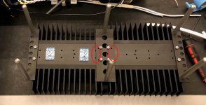
2) Rectifier holes on the bottom side of the regulator heatsinks partially covered. See photo attached.
3) Rectifier heatsink a bit close to top plate.
4) Space for the regulator heatsinks quite tight to the Aux Tx.
1) is a drawing error.
We shall ship to you 6x M4-M3 adaptor screws at our cost.
2) can be rectified by moving the two inner rectifier bridges away from the centre by 6mm or so.
There is still enough space away from the outboard rectifier bridges.
You only need to drill and tap 8x M3 holes.
If you prefer not to drill & tap, we can supply you with a new mounting plate with cutouts to solve the problem
3) is because we designed for GB1 maximum height for some AMerican transformers.
The Toroidy transformers used by most are much lower in height.
And therefore you can have a better balanced use of space by shortening those 6x standoffs by 4~5mm.
If you do not have access to a lathe, you can send them back to CeeVee and he will shorten them for you.
Please get in touch with him directly for arrangements.
4) is a result of the fact that Toroidy no longer produce 15VA toroids.
The 20VA version is just a few mm higher, but space was tight before anyhow.
We can make some 4~5mm extra space by using a set of 3 new mounting plates to redistribute the regulator heatsink positions.
So they solve 2 problems (2&4) in one solution.
To summarise :
1) will be solved at our cost.
3) is functional but not perfect. Send them back, we'll do the mod for you.
2) will require you to redrill and tap 8 holes.
If you wish to have the perfect solution for (2) & (4), then we need to make a set of 3 new plates for you.
I shall pay for those out of my own pocket, as it is my mistake and not CeeVee's.
But I shall very much appreciate if you could contribute half of the cost (20€) to reduce my pain. 🙂
I'll pay postage for all subscribers in any case, for screws, standoffs and optionally new plates.
Hope this is a fair & satisfactory workaround to all,
Patrick
.
We are pretty confident that these are the only ones, due to a drawing version error.
My apologies, to you all and to CeeVee. 100% not his fault.
We have 4 issues, 2 are must-correct, the other 2 optional :
1) Front panel holes for protection board TO220 devices wrongly drilled to M4.
2) Rectifier holes on the bottom side of the regulator heatsinks partially covered. See photo attached.
3) Rectifier heatsink a bit close to top plate.
4) Space for the regulator heatsinks quite tight to the Aux Tx.
1) is a drawing error.
We shall ship to you 6x M4-M3 adaptor screws at our cost.
2) can be rectified by moving the two inner rectifier bridges away from the centre by 6mm or so.
There is still enough space away from the outboard rectifier bridges.
You only need to drill and tap 8x M3 holes.
If you prefer not to drill & tap, we can supply you with a new mounting plate with cutouts to solve the problem
3) is because we designed for GB1 maximum height for some AMerican transformers.
The Toroidy transformers used by most are much lower in height.
And therefore you can have a better balanced use of space by shortening those 6x standoffs by 4~5mm.
If you do not have access to a lathe, you can send them back to CeeVee and he will shorten them for you.
Please get in touch with him directly for arrangements.
4) is a result of the fact that Toroidy no longer produce 15VA toroids.
The 20VA version is just a few mm higher, but space was tight before anyhow.
We can make some 4~5mm extra space by using a set of 3 new mounting plates to redistribute the regulator heatsink positions.
So they solve 2 problems (2&4) in one solution.
To summarise :
1) will be solved at our cost.
3) is functional but not perfect. Send them back, we'll do the mod for you.
2) will require you to redrill and tap 8 holes.
If you wish to have the perfect solution for (2) & (4), then we need to make a set of 3 new plates for you.
I shall pay for those out of my own pocket, as it is my mistake and not CeeVee's.
But I shall very much appreciate if you could contribute half of the cost (20€) to reduce my pain. 🙂
I'll pay postage for all subscribers in any case, for screws, standoffs and optionally new plates.
Hope this is a fair & satisfactory workaround to all,
Patrick
.
Attachments
To help us get organised, please indicate your choice of solution as follows :
a) DIY (no action from us required other than M3/M4 adaptor screws)
b) Standoff shortening (send 6x standoff back to us for trimming off 5mm, + adaptor screws from us)
c) Perfect solution (as in b, but with 3 new regulator heatsink mounting plates)
Please help to fill in the list as follows (example):
Nickname Solution (c)
Once we hear from everyone, we shall proceed to make the necessary parts.
We shall then inform you before shipment.
Many thanks in advance,
Patrick
Coming from a software dev background, i started using git/github for versioning all my schematics/specs/notes/BOMs etc, a bit of a learning curve for the uninitiated but could be worth it, since you can easily track changes over time and help ensure there are no regressions. But i think for large projects like this it's near impossible to have everything flawless, kudos to EUVL and CeeVee for trying to make everyone happy.
Looking forward to the shots of the finished builds with these boxes, they look eye-watering for sure!
Looking forward to the shots of the finished builds with these boxes, they look eye-watering for sure!
You can see quite a few of those from previous batches.
F5X -- the EUVL Approach - The Build Thread
Patrick
F5X -- the EUVL Approach - The Build Thread
Patrick
That center bracket connecting regulator heatsinks has another pair of holes. If you mount it by those, the whole assembly becomes a bit longer, but it still fits. The diodes have just enough clearance this way. This is what I did, I have PSU done and given first fit in the case, looks alright so far
The spacing of holes for regulator PCB stand-offs is off, again, a non-issue really
The spacing of holes for regulator PCB stand-offs is off, again, a non-issue really
Hi Soldersober,
M4 to M3 adapter :
Screw Thread Adapters
but i bought already so can send when i receive them.
Making the heatsink assembly longer means that the small accessories transformer that bolts on the back plate will most probably not fit.
C
M4 to M3 adapter :
Screw Thread Adapters
but i bought already so can send when i receive them.
Making the heatsink assembly longer means that the small accessories transformer that bolts on the back plate will most probably not fit.
C
Last edited:
- Home
- Group Buys
- GB F5X Amp final build Cases