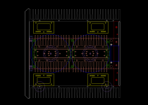
> Making the heat sink assembly longer means that the AUX transformer on the rear bracket will not fit.
Fully correct.
Let me show you what Solution (C) looks like, before you decide.
It is for me a much better solution.
And I do want you to have a deserving case to build the amp with.
Patrick
.
Fully correct.
Let me show you what Solution (C) looks like, before you decide.
It is for me a much better solution.
And I do want you to have a deserving case to build the amp with.
Patrick
.
Attachments
DIY at it's best no degrading of quality of final build....bravo.
Still if we go for an harmonized solution, Pratick has outlined it.
Still if we go for an harmonized solution, Pratick has outlined it.
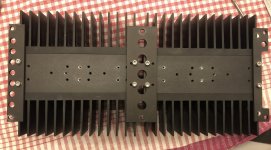
One more mistake, unfortunately.
I vaguely remember that I also have this on my own example.
The two important holes for holding the MOSFETS on the regulator heat sink are OK.
But there us a mismatch for the other two mounting holes.
Two simple solution :
1) Just use a female/female standoff to hold the height of the PCB while soldering the MOSFETs.
After that the PCB is held only by the MOSFETs.
But since there is no real mechanical load, this is just fine.
No machining required.
2)If you have good mechanical skills, then re-tapping two M3 holes should also not be a great challenge.
Again my apologies,
Patrick
.
Attachments
Morde DIY (a)
soldersober DIY (a) or better even please post part number for M3-M4 thingy
s610adam DIY (a) - I'm also fine getting the adaptors with all the other fun stuff to order.
And I'm still blown away by how nice it is to get to build this F5X 🙂
soldersober DIY (a) or better even please post part number for M3-M4 thingy
s610adam DIY (a) - I'm also fine getting the adaptors with all the other fun stuff to order.
And I'm still blown away by how nice it is to get to build this F5X 🙂
As Carlos mentioned, we already ordered adaptor screws for all.
So we'll send to each a set of 6.
But if you want more of those, here is the link :
Thorlabs - AP4M3M Adapter with External M4 Threads and External M3 Threads
They also have outlets in Europe. Probably also Asia.
Patrick
So we'll send to each a set of 6.
But if you want more of those, here is the link :
Thorlabs - AP4M3M Adapter with External M4 Threads and External M3 Threads
They also have outlets in Europe. Probably also Asia.
Patrick
Morde DIY (a)
soldersober DIY (a) or better even please post part number for M3-M4 thingy
s610adam DIY (a) - I'm also fine getting the adaptors with all the other fun stuff to order.
markus22ch DIY (a)
soldersober DIY (a) or better even please post part number for M3-M4 thingy
s610adam DIY (a) - I'm also fine getting the adaptors with all the other fun stuff to order.
markus22ch DIY (a)
Many congratulations. 🙂
Maybe a short summary of all the workarounds that you made ?
Glad to know there are no more issues.
Patrick
Maybe a short summary of all the workarounds that you made ?
Glad to know there are no more issues.
Patrick
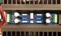
In addition to the Cap Mx new tapped holes that I showed earlier, I shortened the Cap Mx standoffs by 5mm to get more room between the sink and the top cover. Cap Mx PCBs are resting on 10mm standoffs and the Mosfets. I did not make new tapped holes for the standoffs.
Protection PCB’s to-220 devices are floating in the air and I’ve put some kapton tape for insulation between the devices and the front panel. I noticed that they barely even get warm with my choise of relays. I will fix this eventually with the M4/M3 adaptor screws.
Protection PCB’s to-220 devices are floating in the air and I’ve put some kapton tape for insulation between the devices and the front panel. I noticed that they barely even get warm with my choise of relays. I will fix this eventually with the M4/M3 adaptor screws.
My own CapMx PCBs are sitting on 5mm standdoffs. 😉
CeeVee has already received the adaptor screws and tested them to do the job.
So he will ship them out once your solution choice is confirmed.
Patrick
CeeVee has already received the adaptor screws and tested them to do the job.
So he will ship them out once your solution choice is confirmed.
Patrick
Finally I got my case today, looks great! Due to the current situation, the delivery got stuck.... next Friday I will get the toroids from Poland. It goes forward!
Markus
Markus
Before you order parts, we are testing some new rectifier diodes instead of MSR1560.
So save those first. Will explain when we have results.
Patrick
So save those first. Will explain when we have results.
Patrick
ok, thanks for the hint, I will wait. Till now only the toroids and the PRP resistors are ordered 🙂
You can start with the amp and the protection board first.
Those are well proven, and no change required.
The diode is just something new that we wan to try.
Not that the ones in the BoM will not work.
Patrick
Those are well proven, and no change required.
The diode is just something new that we wan to try.
Not that the ones in the BoM will not work.
Patrick
Just to clarify on problem #4. What is the transformer clearance currently without any fixes to moving the regulator heatsink?
- Home
- Group Buys
- GB F5X Amp final build Cases