The US shipping should be piece of cake - I just need a source for cheap bubble wrap envelopes and figure out if I can print stamps online. I have finally heard from the shipping company and our 3 m^3 will arrive tomorrow between 8 and 9. 😀
We were told that shipping would take 5 weeks, but it has taken 7. 🙁
I'll be at Emerald bay this weekend, so I wont be able to send any boards before next week, but if the boards look unharmed, I'll open for orders tomorrow.
We were told that shipping would take 5 weeks, but it has taken 7. 🙁
I'll be at Emerald bay this weekend, so I wont be able to send any boards before next week, but if the boards look unharmed, I'll open for orders tomorrow.
Cviller,
Per your gbf5_guide.pdf document, you stated that you had substituted BC transistors for the ZTX transistors. As long as the collector/base/emitter designations are adhered to, is it okay to subsitute the equivalent ZTX transistors instead? I know the 'curve' then will be on the opposite side. The reason I ask is because the Tech DIY Company Store offers these transistors with their F5 parts package.
Best,
Anand.
For small items like PCBs, you may consider using the Priority Mail Small Flat Rate Box. The box is free and it has a retail shipping price of $4.95 — one price, regardless of weight. The online price is even lower, $4.80.
Looking around for bubble mailers, I found that most of the smaller ones price at around $.10/ea.. Here is one source: http://www.packagingprice.com/forms/product_detail.cfm?categoryID=10019&productID=515 Hope this helps.
Cviller,
Per your gbf5_guide.pdf document, you stated that you had substituted BC transistors for the ZTX transistors. As long as the collector/base/emitter designations are adhered to, is it okay to subsitute the equivalent ZTX transistors instead? I know the 'curve' then will be on the opposite side. The reason I ask is because the Tech DIY Company Store offers these transistors with their F5 parts package.
Yeah, you got it right. 😉
The BC's and ZTX's have the same pin sequence - just flipped.
westend and dgss, thanks for your tips!
Now my boards are here!!! 😀
I have re-enabled my simplistic little order site her:
http://viller.eu/gb
I should be able to ship sometime next week or perhaps the week after, if I need to wait for bubble wrap envelopes.
I have re-enabled my simplistic little order site her:
http://viller.eu/gb
I should be able to ship sometime next week or perhaps the week after, if I need to wait for bubble wrap envelopes.
🙂Please tell me how to make payment for the F5 PcB,s🙂 Thank You very much Sir.
Payment is easiest with paypal. I had a slow week at work when I made my order site, so I figured out how to connect it to paypal, which means if you go to checkout you'll get transferred to paypal.
So just go to http://viller.eu/gb and it should be very easy.
hey cviller, do you have any F4 boards left over?
F4 boards? I have F5, but F4s are only on the drawing board...

a couple of questions...
OK , I just read all 89 pages ot this thread and some of the various side threads and links, and most of my questions were answered somewhere along the way.... however I do have a couple of questions left 😀
1) for the PS there seems to be 2 possible configurations CRC and CLC.
What are the pros/cons of CLC
2)I did not see much talk about pre-amps that work well with the F5.
I have a BOZ, will this combo be ok?
3)also not much talk of speaker pairings.
I am considering both building and or possibly purchasing speakers specifically for the F5.
This is probably not the right place to ask for possible suggestions for speakers or kit designs but I'm asking anyway 😀
Thanks to all involved!!
Reading the whole thread????? Impressive!! 
1) CLC is more expensive because you need to get some large inductors. If you get something decent, your filter will reject more of the charging noise. CRC is a lot better than simply C, but the circuit also rejects some noise. You can see the noise from charging as 120hz if you're running it out of 60hz outlets.
2) It has 15db gain, which is lower than most commercial power amps, but you should be all-right with just about any preamp.
3) As for speakers pairing, you can also try what ever you like, but the F5 is very detailed which might be too much for some speakers, but it also depends on the ears. 😉
Thanks for the response!!
Will inductors fit on the power supply PCB ?
Yeah, I have made some holes for them. If you show a picture I might be able to tell you if it will work. But if you're unsure about it I would suggest to just go for the CRC. 😀
The boards look very good and have been recommended to me by past builders of this amp. Order has been selected and paid. Thanks for your efforts.
Thanks. I'm still waiting on the envelopes, but I should be able to send after labor day. Scheduled delivery for the envelopes is 09/08/2009.
Thanks for your patience!
Thanks for your patience!
Chris,
I'm about ready to power up my F5 that I built using your boards. Just Beautiful!
Remember I owe you a beer at BA in October!
Before I put power to them, I have a question about the voltage present on the LED solder pads, are they 24V or 48V?
ie; positive referenced to ground or Positive referenced to Negative rail?
Checking the continuity, they seems to be referenced to ground. But I thought I should ask before I burn up my LEDs. 😱
I should have asked before I soldered in Resistors calculated for 24V, but it's not too late to change them if I need to!
Thanks,
Ron
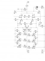
Yes, the led is between gnd and a resistor connected to V+. You can select R35 to give you the desired amount of light from your diodes. The value I have shown is very conservative compared to papas (10k in the F4 schematics!!!).
Yes, the led is between gnd and a resistor connected to V+. You can select R35 to give you the desired amount of light from your diodes. The value I have shown is very conservative compared to papas (10k in the F4 schematics!!!).
Did I miss something..............?????????
or am I just lost again.
Thanks Chris,
But.......I think you are thinking of the other R who's value is 22K not R35 😀
R35 value for 1 blue LED is 1.2Kohms.
At 10K your not going to light up a LED. With 24V supply and 3V forward drop across the LED, your only going to supply 2.5mA.
Thank you for being quick on the keyboard though!🙂
Ron
OK,
now that I have looked up Papa's F4 schematic, it am totally confused. 😕
It looks like he has a 22.1K resistor for his LED.
Yet, when I used an online LED resistor calculator for a pair of Blue LED 3.3V 20.mA in series driven by a 24V source, I came up with a R of 870 Ohms and .58 watts. Rounding up I have (and installed) a 1K Ohm 1Watt.
This seems radically different than either 10K or 22K.
Help a brother understand what the difference is.
Lost again
Ron
Attachments
- Status
- Not open for further replies.
- Home
- Group Buys
- Gb: F5 Pcb