Re: initial rail reading
Most variacs go over 120v to 130v or so. You have to be careful.
alazira said:
Hi,
This was my 1st amp build (thanks N. Pass, C. Viller for boards, and U.Dailey for step-by-step power supply pictorial) and I bought my 1st multimeter and variac. I put everything together, plugged it in and slowly turned up the voltage to 125. I was very happy to see the little led lights glow. When I first measured the rails they were 29vcd!😱 😱
Some things I thought were perhaps my toroid was incorrectly labled (antek 300va 18x18) or my variac was defective. I had to turn it down to 105 volts to achieve 24vdc rails. My initial reading across r11 was 0. After p1/p2 adjustment my rails were 25 at 120volts and generally I have measured 22 to 23.5 average off the mains.
Most variacs go over 120v to 130v or so. You have to be careful.
Small changes on the variac can make huge changes on the output dc voltage rails in your circuit, especially with solid state circuits that work under 50V for the most part. Tube circuits on the other hand are high voltage circuits and you have a little bit more legroom (and tubes are a little more tolerant). Either way, turn up the variac slowly and measure at intermittent points before going all the way to 120V AC.
Best of luck and enjoy your new F5!
Cviller,
What is the name or part number of the thermistor you showed in this picture:
Anand.
Best of luck and enjoy your new F5!
Cviller,
What is the name or part number of the thermistor you showed in this picture:
An externally hosted image should be here but it was not working when we last tested it.
Anand.
Can I have a clarification on Q3 and Q4?
The BOM I used calls for Q3 to be FQA19N20C which is N channel. The schematic calls for IRFP9240 which is P channel. The board also marks Q3 as P channel.
The same BOM calls for Q4 to be FQA12P120... you guesed it, P channel.
I'm assuming that the board is correct, and the BOM is backwards.
So is it acceptable to use the FQA19N20C for Q4 and the FQA12P120 for Q3?
Thank you.... almost done!
I refer you to the original article by Mr. Pass at the First Watt website:
http://www.firstwatt.com/downloads/F5 Power Amplifier for PassDIY.pdf
http://www.firstwatt.com/downloads/F5 Power Amplifier for PassDIY.pdf
RKH said:I refer you to the original article by Mr. Pass at the First Watt website:
http://www.firstwatt.com/downloads/F5 Power Amplifier for PassDIY.pdf
would you mind being more specific? Some of this stuff doesn't come natural to all of us. If you know that answer, please state so.
specialidiot said:Can I have a clarification on Q3 and Q4?
The BOM I used calls for Q3 to be FQA19N20C which is N channel. The schematic calls for IRFP9240 which is P channel. The board also marks Q3 as P channel.
The same BOM calls for Q4 to be FQA12P120... you guesed it, P channel.
I'm assuming that the board is correct, and the BOM is backwards.
So is it acceptable to use the FQA19N20C for Q4 and the FQA12P120 for Q3?
Thank you.... almost done!
If THIS is the BOM that you used it was incorrect, I have made the changes to swapped Q3 & Q4. Sorry for the confusion.

Jim
max426 said:
If THIS is the BOM that you used it was incorrect, I have made the changes to swapped Q3 & Q4. Sorry for the confusion.
Jim
That's the one! Thank you Jim... Something didn't feel right, I have one channel ready for power and as I was putting Q3 into the board I spotted the error.
I appreciate your clear follow up without requesting me to read another 13 pages of technospeak.
My apologies. Page 7 (figure 6) of the article has the original schematic and that will allow you to see which device goes with which rail. It now appears that the BOM has been corrected.
Good luck!
Ryan
Good luck!
Ryan
nycavsr2000 said:Cviller,
What is the name or part number of the thermistor you showed in this picture:
http://viller.eu/audio/2009jan_gbf5/P1070474_wiring1.jpg
Anand.
I don't have any thermistors in the photo. You can use CL60 thermistors for soft-starting the toroid, but that's another story. 😉
I don't have any thermistors in the photo. You can use CL60 thermistors for soft-starting the toroid, but that's another story.
Cviller,
Thanks for the clarification! So what are the small square devices you have in the bottom of the picture? Is it just a fancy terminal block?
Thanks,
Anand.
nycavsr2000 said:So what are the small square devices you have in the bottom of the picture?
http://search.digikey.com/scripts/DkSearch/dksus.dll?Detail&name=MB352-ND
!!!!
Peter,
My bad! Thanks! I'm so used to your boards where the diodes and ps capacitors are one integral unit, my brain just stopped working, duh!
Anand.
Peter,
My bad! Thanks! I'm so used to your boards where the diodes and ps capacitors are one integral unit, my brain just stopped working, duh!
Anand.
nycavsr2000 said:Small changes on the variac can make huge changes on the output dc voltage rails in your circuit, especially with solid state circuits that work under 50V for the most part. Tube circuits on the other hand are high voltage circuits and you have a little bit more legroom (and tubes are a little more tolerant). Either way, turn up the variac slowly and measure at intermittent points before going all the way to 120V AC.
Best of luck and enjoy your new F5!
Anand.
Novice mistake. Next time I will definitely measure the rail voltage as I turn the variac up. In fact, I will test the power supply before integrating it with the amp.
I'm up and running. Still waiting on a jewel lamp for the front panel, then I just have to dress it up and rack it.
Thanks to everyone for your patient assistance!
Thanks to everyone for your patient assistance!
I'm up and running. Still waiting on a jewel lamp for the front panel, then I just have to dress it up and rack it. Thanks to everyone for your patient assistance!
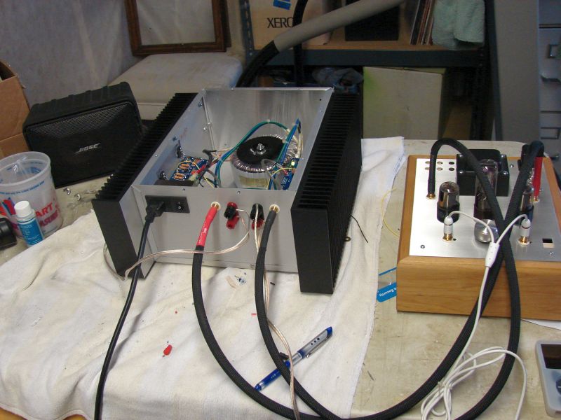
That looks like a DIYenclosures 1013 chassis, and Antek transformers you are using. Nice work. Some very nice oversized heatsinks 😱
Anand.
nycavsr2000 said:
That looks like a DIYenclosures 1013 chassis, and Antek transformers you are using. Nice work. Some very nice oversized heatsinks 😱
Anand.
Good eye, Anand. I'm surprised you didn't call out the Conrad heatsinks though.

I got it running Monday night late so I didn't have time to wait for the temp to stabilize and had to wait 24 hours before I could tweak the pots. Its surprised me how warm the thing got!
Chris,
We just got your boards today.
Thanks for sending it again.
Did you received the first package?
What's the size of your heatsink "specialidiot" ?
i got 2 case with 40 cm Lx 13.1 Wx 3cm H on each side.
I really hope it will be sufficient.
Cheers
Henry
We just got your boards today.
Thanks for sending it again.
Did you received the first package?
What's the size of your heatsink "specialidiot" ?
i got 2 case with 40 cm Lx 13.1 Wx 3cm H on each side.
I really hope it will be sufficient.
Cheers
Henry
_henry_ said:?
What's the size of your heatsink "specialidiot" ?
The heatsink is a Conrad MF35-151.5
Specs herehttp://www.conradheatsinks.com/products/flat100_350.html
Yes, I still have plenty of boards left and yes, I use paypal.
You can order through http://viller.eu/gb
You can order through http://viller.eu/gb
- Status
- Not open for further replies.
- Home
- Group Buys
- Gb: F5 Pcb