Thanks, and yes i look forward. In previous posts i already show the direction i am going.Well one thought is, I think it is a good plan. A very good plan. A waveguide should minimize the baffle edge diffraction on the tweeter. It also helps reduce the impact of CTC spacing between the mid and the tweeter, which means that your (possibly) non-optimal CTC spacing matters less than it would with a flat baffle. Anything you can do to use that beautiful cabinet is well worth doing.
Another thought I had is that there is no point in dwelling on the "mistakes" you made in 2006, or what you should have done differently. 16 years ago, we did not have the simulation tools we have now, nor did we have the widespread consensus knowledge of the importance of Directivity Index, Power Response, and Early Reflections. These concepts may have been known by the top experts such as Toole, Linkwitz, Geddes, Voecks, but the concepts were not generally known or accepted. Looking back at what you did in 2006, I am sure there are things you would do differently, but that does not mean that 2006 was a "mistake".
So hopefully the tone of responses in this thread can point forward toward the future, rather than look backward at what could have been done in 2006.
j.
Looking back at what you did in 2006, I am sure there are things you would do differently
allowing us to establish and understand what was wrong with the original build will help others to avoid making the same mistakes
@ctrlx , i do not have a good picture of the original baffle, but your question is a valid one. When i designed it, i had to decide on the acoustic centre of each driver. So desktop research and the assumption i then made was the front of the magnet I believe. Measurements were not very conclusive, and also quite coarse then. A year later when i got a better audio interface (m-audio) i was able to perform more precise and repeatable results, the AC of the drivers turned out to be around the depth where the voicecoil carrier is connected to the cone. With the accuton midrange that was some 12mm difference. With the tweeter it was within the tolerance of the resolution of the measurements ( ~2mm if i remember correctly) .
So i altered the baffle to what you see on the picture, the midrange being moved back 12mm. I then got acceptable results in the xo design, that correlated with measurements, be it for midrange -tweeter xo , and only on-axis. And based on minimum phase.
Because of my work i then could no longer spend enough time on the design, so it stayed liked that for quite some time.
As you can read between the lines, the time dimension was and still is important for me.
That is why i also check the impulse response in Vituixcad, next to about everything else one can do in Vituixcad ;-)
And why i also focus now on same polarity of the drivers. In the current config the woofers are in reversed polarity.
And why i also focus now on same polarity of the drivers. In the current config the woofers are in reversed polarity.
Today i was able to meausre the tweeter (Accuton C30-6-024 ) with the @augerpro designed waveguide, including off-axis responses in 10 degree steps.
This time the WG was made including a mounting-flange so i could bolt it on the enclosure. To get a smoothtransition a baffle add-on made and placed, with tape covering gaps.


The ridge at ~ 3.9kHz is a tweeter thingy i still need to look into.
Something going in in the range ~9kHz upwards, perhaps @augerpro can respond to this?
This time the WG was made including a mounting-flange so i could bolt it on the enclosure. To get a smoothtransition a baffle add-on made and placed, with tape covering gaps.
The ridge at ~ 3.9kHz is a tweeter thingy i still need to look into.
Something going in in the range ~9kHz upwards, perhaps @augerpro can respond to this?

Nice progress. The resonance behavior at 3.9k is interesting. It looks like a +1.5 dB resonance at 3.9k, preceded by a -1.5 dB suckout at 3.2k. It will be interesting to see what you find.
The waveguide should nicely match up the directivity of the tweeter with the mid. What is your thoughts about a crossover frequency?
The waveguide should nicely match up the directivity of the tweeter with the mid. What is your thoughts about a crossover frequency?
Diffraction, on axis dip, off axis peak moving with frequency.Something going in in the range ~9kHz upwards
1984 Bass64 for commodore...http://www.renatogiussani.it/pdf/bass64-reflex.pdfOk, today we have all the tools that, at that time, were unobtainable
Last edited:
For filter design at that time i used Paul verdone's Excel with an c-programmed plugin.
And a German tool for impulse measurements and fr conversion.
Long gone since( unfortunately also my dossiers from that period).
And a German tool for impulse measurements and fr conversion.
Long gone since( unfortunately also my dossiers from that period).
I wrote a program for my Sharp PC1500 programable calculator (with a printer) to make the TSP calculations for closed and vented cabinets. The only useful programing I ever did. In Basic. The problem at that time was to get real TSP for the available chassis.
Hardly anyone in loudspeaker DIYS understood what I was doing at that time. People were used to try and error with vague cabinet size information. Like "30-4000Hz in 30-50l reflex".
VISATON denied to give TSP, considered them trade secrets. Morons! Other brands seemed to simply invent them freely. So I went for the better, international know brands, what probably saved me from using a lot of bad, cheap chassis.
X-over was done from a huge stash of coils, caps and resistors, listening to a reference speaker on one channel of a stereo amp and the new build on the other. About 30 pounds of copper to choose from...
When I had my first measuring system, years later, I was surprised how well the "ear build" x-over's performed.
Before I could measure response, I sometimes needed weeks until I liked the sound. Some chassis where just impossible to match. Today we know why when we measure them. Which build up quite a stock of unused drivers.
I read any of the few speaker builder books that existed, about 99 times each...minimum.
Clio on 1990 are ready maybe some year before ,we use xcross and xbass with 286i with coprocessor LOL
lucky at the time we have a small anecoic room with B&K by local loudspeaker industry that partner work in
lucky at the time we have a small anecoic room with B&K by local loudspeaker industry that partner work in
Some intermedeate results in getting the midrange baffle shape in shape.
The current baffle
The current baffle plus some 2cm thick ecology absorbing material (ECOABSJDI)
The current baffle plus some 6mm thick white carton with straight opeingin for midrange and some rounding towards the baffle edge (White01Baffle)
The current baffle plus some 12mm thick foamboard and white carton with waveguidish opening for midrange and significant rounding towards the baffle edge (WG01Baffle)
In addition and only on-axis measurements due to time-constraints:
The current baffle plus some 6mm thick white carton with straight opening for midrange and a 170mm diameter carton rim around the opening and some rounding towards the baffle edge (White02Baffle)
The current baffle plus some 12mm thick foamboard and white carton with waveguidish opening for midrange plus a 170mm diameter carton rim and significant rounding towards the baffle edge (WG02Baffle)
Analysis thusfar:
First of all i only wish i could have made off-axis measurements for the "02" cases. Anyhow I am getting closer to a much better baffle shape for the midrange.
- The baffle shape has a significant impact on the frequency responses AND the power-DI
- The ECOABS was a Just Do It thing and the audible differences were so much better despite the on-axis cancellation around 1700Hz that it triggered me to go find a solution without having to completely rebuild the baffle.
- The Waveguide option was chosen to also allow for a waveguide on the tweeter, thus need for some added thickness aound the tweeter waveguide and midrange. The difference with the WhiteBaffle is the amount of thickness and the edge shape of the midrange opening.
- It also appears to be the best result sofar for the midrange as its of axis responses show a smooth gradient in the off-axis responses and in the Power-DI curve. As an extra it narrows the directivity a bit in the midrange and thus also a bit higher output in that region. (like with tweeter waveguides).
- The extra rim (i studied the D&D 8C and Kii Three designs) does help to lessen the dip at 1700-2100Hz. Yet to see what the directivity effects will be.
- Somehow, if i could solve the dip, the ECOABS baffle would be the best option i think based on the measurements. But i have not yet figured a way to deal with the dip.
Technical info:
Measurements at 100cm from original baffle. Made in different sessions, and i do not always get the calibration of Arta right ;-~ , so i scaled the responses to match at low frequencies and the resonance peak at 9500 Hz.
Used VituixCAD for IR to FR with same settings for all measurements and loaded into VCAD to see and analyse results, showing bothe the responses till 90 degrees off-axis and the Power/DI responses:

CurrentBaffle:
.png")

The ECOABSJDI:
.png")

The White01Baffle:
.png")

The WG01:
.png")

The following are only on-axis, and just to see if it matters to ad a rim around the opening of the midrange to fill the dip at ~ 1700-2100 Hz.
White02Baffle:
.png")
WG02Baffle:
.png")
The current baffle
The current baffle plus some 2cm thick ecology absorbing material (ECOABSJDI)
The current baffle plus some 6mm thick white carton with straight opeingin for midrange and some rounding towards the baffle edge (White01Baffle)
The current baffle plus some 12mm thick foamboard and white carton with waveguidish opening for midrange and significant rounding towards the baffle edge (WG01Baffle)
In addition and only on-axis measurements due to time-constraints:
The current baffle plus some 6mm thick white carton with straight opening for midrange and a 170mm diameter carton rim around the opening and some rounding towards the baffle edge (White02Baffle)
The current baffle plus some 12mm thick foamboard and white carton with waveguidish opening for midrange plus a 170mm diameter carton rim and significant rounding towards the baffle edge (WG02Baffle)
Analysis thusfar:
First of all i only wish i could have made off-axis measurements for the "02" cases. Anyhow I am getting closer to a much better baffle shape for the midrange.
- The baffle shape has a significant impact on the frequency responses AND the power-DI
- The ECOABS was a Just Do It thing and the audible differences were so much better despite the on-axis cancellation around 1700Hz that it triggered me to go find a solution without having to completely rebuild the baffle.
- The Waveguide option was chosen to also allow for a waveguide on the tweeter, thus need for some added thickness aound the tweeter waveguide and midrange. The difference with the WhiteBaffle is the amount of thickness and the edge shape of the midrange opening.
- It also appears to be the best result sofar for the midrange as its of axis responses show a smooth gradient in the off-axis responses and in the Power-DI curve. As an extra it narrows the directivity a bit in the midrange and thus also a bit higher output in that region. (like with tweeter waveguides).
- The extra rim (i studied the D&D 8C and Kii Three designs) does help to lessen the dip at 1700-2100Hz. Yet to see what the directivity effects will be.
- Somehow, if i could solve the dip, the ECOABS baffle would be the best option i think based on the measurements. But i have not yet figured a way to deal with the dip.
Technical info:
Measurements at 100cm from original baffle. Made in different sessions, and i do not always get the calibration of Arta right ;-~ , so i scaled the responses to match at low frequencies and the resonance peak at 9500 Hz.
Used VituixCAD for IR to FR with same settings for all measurements and loaded into VCAD to see and analyse results, showing bothe the responses till 90 degrees off-axis and the Power/DI responses:
CurrentBaffle:
The ECOABSJDI:
The White01Baffle:
The WG01:
The following are only on-axis, and just to see if it matters to ad a rim around the opening of the midrange to fill the dip at ~ 1700-2100 Hz.
White02Baffle:
WG02Baffle:
Hi Jan - when I look at the current baffle, I see some diffraction funkiness between 1.5k - 3k. The horizontal polar curves change a lot from 0 - 60 degrees, which would make it difficult to apply EQ in this frequency range.
Now comparing that to the ECOABSJDI, we see that the horizontal polar curves are very similar to the on-axis curves. This reveals a possible small resonance at about 2.5k. Since the resonance is observable in all the polar curves, you could EQ it down. Overall I like how it looks.
When I look at the WG01, I like how the DI is very smooth from 1k to 4k. But above 4k, there is some funkiness in the power response and the ER curves.
I am having a hard time visualizing what the various baffle options look like... could you post some photos?
j.
As @hifijim pointed out correctly, the pictures of the baffle modifications are missing.
Here they are:
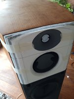
The current baffle

Note: the trapezium shaped part is 6mm thick.
The current baffle plus some 2cm thick ecology absorbing material (ECOABSJDI)
.jpg")
The ECOABSJDI is about 2.5cm thick.
The frequency response changes are quite close to a diffraction sim in VituixCAD with a baffle widened by 100mm (362 vs 262):

The current baffle plus some 6mm thick white carton with straight opening for midrange and some rounding towards the baffle edge (White01Baffle)
.jpg")
Note: here is also visible the use of playdough to quickly see what element/aspect has impact on response.
The current baffle plus some 12mm thick foamboard and white carton with waveguidish opening for midrange and significant rounding towards the baffle edge (WG01Baffle)

During testing i added tape over all edges to reduce their impact.
In addition and only on-axis measurements due to time-constraints:
The current baffle plus some 6mm thick white carton with straight opening for midrange and a 170mm diameter carton rim around the opening and some rounding towards the baffle edge (White02Baffle):

The current baffle plus some 12mm thick foamboard and white carton with waveguidish opening for midrange plus a 170mm diameter carton rim and significant rounding towards the baffle edge (WG02Baffle)

The last picture also shows some 3D printed waveguides for midrange, to be combined with different baffle addon shapes to find a good combination. The next test objective ;-)
Here they are:
The current baffle
Note: the trapezium shaped part is 6mm thick.
The current baffle plus some 2cm thick ecology absorbing material (ECOABSJDI)
The ECOABSJDI is about 2.5cm thick.
The frequency response changes are quite close to a diffraction sim in VituixCAD with a baffle widened by 100mm (362 vs 262):
The current baffle plus some 6mm thick white carton with straight opening for midrange and some rounding towards the baffle edge (White01Baffle)
Note: here is also visible the use of playdough to quickly see what element/aspect has impact on response.
The current baffle plus some 12mm thick foamboard and white carton with waveguidish opening for midrange and significant rounding towards the baffle edge (WG01Baffle)
During testing i added tape over all edges to reduce their impact.
In addition and only on-axis measurements due to time-constraints:
The current baffle plus some 6mm thick white carton with straight opening for midrange and a 170mm diameter carton rim around the opening and some rounding towards the baffle edge (White02Baffle):
The current baffle plus some 12mm thick foamboard and white carton with waveguidish opening for midrange plus a 170mm diameter carton rim and significant rounding towards the baffle edge (WG02Baffle)
The last picture also shows some 3D printed waveguides for midrange, to be combined with different baffle addon shapes to find a good combination. The next test objective ;-)
Attachments
If you don't change anything in the position, the response will not change. Your tweeter is still too close to the upper edge.
You do not need to do your experiments on the real cabinet, a panel it's size will do. Preferable not from wood, but some foam (XPS?) you can simply carve with a knife.
Good luck!
You do not need to do your experiments on the real cabinet, a panel it's size will do. Preferable not from wood, but some foam (XPS?) you can simply carve with a knife.
Good luck!
Yesterday i had some time to do some tests, and focused on the Tweeter, and measured at 100cm from baffle on-axis only with Arta and converted to FR in VituixCAD using same settings for all measurements in this post.
First the tweeter without its grille in the original baffle, then with ECOABS wedges left and right:

Red dash-dot is the tweeter in the original baffle. The wedges do smoothen the on-axis response a bit. So not bad at all despite the placement of the tweeter in the enclosure.
Then with the Waveguide mounted without any baffle add-on's followed by the ECOABS wedges other way around:

Note: The blue dash-dot is without de wedges.
Basically the response between 1 and 4kHz is strongly influenced by the baffle construction, as expected. Is next topic on the list to look into.
Also the strong cancellation at 10.2 kHz followed by a peak is clearly something of the waveguide. Given the short wavelength ~2.5-3cm i suspected the top-bottom part of the waveguide mouth to be the area to focus on. So playing with playdough eventually led to this result (the Cyan curve), way better! :

Picture of this playdough mod01:

And today cross-section cut of the playdough (1 day later so the stuff started to dry and thus deform a bit):

I am no expert on waveguides but to me looks like the shape of the termination of the mouth? Will contact @augerpro to look into this. with him.
Note that the picture also shows playdough on the left-right part of the waveguide, but that did not provide an improvement.
So to summarise:
The waveguide needs some adjustments, the baffle surrounding the tweeter waveguide is quite tricky (especially from waveguide to top of enclosure) , but doable, so i can achieve a better directivity match with midrange.
Also no need to change the position of the tweeter which basically is not really possible technically given the enclosure.
First the tweeter without its grille in the original baffle, then with ECOABS wedges left and right:
Red dash-dot is the tweeter in the original baffle. The wedges do smoothen the on-axis response a bit. So not bad at all despite the placement of the tweeter in the enclosure.
Then with the Waveguide mounted without any baffle add-on's followed by the ECOABS wedges other way around:
Note: The blue dash-dot is without de wedges.
Basically the response between 1 and 4kHz is strongly influenced by the baffle construction, as expected. Is next topic on the list to look into.
Also the strong cancellation at 10.2 kHz followed by a peak is clearly something of the waveguide. Given the short wavelength ~2.5-3cm i suspected the top-bottom part of the waveguide mouth to be the area to focus on. So playing with playdough eventually led to this result (the Cyan curve), way better! :
Picture of this playdough mod01:
And today cross-section cut of the playdough (1 day later so the stuff started to dry and thus deform a bit):
I am no expert on waveguides but to me looks like the shape of the termination of the mouth? Will contact @augerpro to look into this. with him.
Note that the picture also shows playdough on the left-right part of the waveguide, but that did not provide an improvement.
So to summarise:
The waveguide needs some adjustments, the baffle surrounding the tweeter waveguide is quite tricky (especially from waveguide to top of enclosure) , but doable, so i can achieve a better directivity match with midrange.
Also no need to change the position of the tweeter which basically is not really possible technically given the enclosure.
You narrow in the dispersion of the tweeter, which makes it ignore the baffle. If you keep on following this path, you will end up using a horn tweeter. That is quite simple to see, if you use a tweeter that is working independent of the baffle, the unsuitable form of the baffle doesn't matter. A very logical process.
Maybe replace the rags with some putty too, so you are not distracted from the real problem.
Maybe replace the rags with some putty too, so you are not distracted from the real problem.
Just got feedback from @augerpro and will get that in test quickly. Horn or waveguide or baffle , it is the impact on radiation of waves i am working on within the limits of the existing enclosure. Within that limitation the objective being to get as smooth as possible on and off axis response.
Actually the challenge is quite satisfactory 😎
Actually the challenge is quite satisfactory 😎
A new tweeter waveguide, this time with cubic splines defined, mimicking the playdough adaptations. Not a bad result:

This is the WGCubic01 waveguide with a 1.5mm shim added (museum carton) with opining as opening in wg.
The red curve the measurement 2 weeks ago, the blue curve with the WGCubic01 and shim but no damping on floor between speaker and mic while measuring.
The purple curve is with damping on floor.
Smoothed 1/12
Next week a full off-axis measurement.
I hope i will be as happy then as today ;-)
- Home
- Loudspeakers
- Multi-Way
- GAYA2-Final, finishing the unfinished after 15 years