Basically, the reason that the higher powered transformer was used, was due to the equipment on hand for using with the lm3875. He carefully tested the amplifier with a test load first, monitoring the amplifier with an oscilloscope and function generator, and found no problems, recording 78watts into his dummy 8 ohm load with the given power supply voltages. I don't see this to be much more of a safety risk than overclocking a computer.
It will be interesting to see the long term effect of the higher power supply voltages. I was the previous owner of the 36vac transformer used, which I had sitting on my shelf, considering making a regulated gainclone, since I didn't want to try the increased supply voltages. In the end, I bought another 2x24vac transformer, which I would recommend for those buying new transformers for their gainclones.
I cranked up the voltage on a bench supply once for am LM3875 (my old inverted one), and when I reached around 50vdc (limit of dual bench supply), the amplifier stopped working. I turned it back down a bit, and it worked again. This was a test without a load, but the amplifier seems to have circuitry to disable itself under high voltages. The amplifier worked just fine afterwards, and I used it for a few months, before building a new one with the non-inverted topology.
--
Brian
jean-paul said:Hi Peter, please bear in mind that the PCB's are also bought by a number of starters that may not see the risk in doing this. They probably read this thread too and may be tempted by successful stories to push devices over their maximum limits. They could have less success in doing so, ending up with damage blaming anyone but themselves. This project is a tempting one for new DIYers also because it is almost a guarantee to a good working good sounding amp. This advice could compromise that goal.
If one persists in challenging the manufacturers absolute maximum limits I would strongly advice in using a speaker protection circuit and secondly to never leave the amp on while one is away from home.
What do the forum rules say about unsafe advice ?
While posing a potential hazard to equipment, it is no more likely to cause bodily harm that using similar voltages in any other electronics project. If someone doing their first project (or 100th project) happens to break something by pushing equipment past a rated limit, then he has no one to blame but himself. That said, there is no garantee that something won't fail well within its rated limits, even though it is less likely. I certainly do not recommend anybody overvolt any component unless they do not mind the increased potential of having that component (and others connected to it) fail. However, in a situation like mine where somebody has a transformer that is a little too high for an LM3875, but they don't want to buy a new one, or even somebody who simply likes to push limits, knowing how rigid the limits really are might be useful. I will of course let everyone know if my amp breaks, or if it has been running fine for several weeks, I will post that.
According to National's datasheet, ±42V is the maximum recommended supply voltage for the LM3875. If you want to exceed that, knowing the risks, then go ahead. There will not be an improvement in sound unless you were clipping during transients because of low rail voltages like I was. The increased heat dissipation must also be considered, and how it will behave with a 4Ohm load is anybody's guess. I personally would not exceed ±48VDC under any circumstances, as the chip would certainly not last long, and I would have preffered to not exceed ±45VDC, had my transformer allowed that.
success, well partially.
I got the amp up and running and then the speakers started making a humming sound. Checked the fuses and they were blown. Put in some new ones and they blew rite away. Off to radio shack to get some more slow blows but I wonder why it is doing this.
I got the amp up and running and then the speakers started making a humming sound. Checked the fuses and they were blown. Put in some new ones and they blew rite away. Off to radio shack to get some more slow blows but I wonder why it is doing this.
Stupid black magic. Well I got some more fuses and everything worked out on the first try. The amp is really weird. The music is alot tighter then my old amp and I can hear alot more of the sounds coming from the music. Vocals are awesome.
An externally hosted image should be here but it was not working when we last tested it.
quick briangt pcb question
From pictures I wasn't able to see this, but as far as grounding is concerned, is the signal ground on the board tied to the channel ground on the board directly (if so, where, i can't see it).
Thanks!
From pictures I wasn't able to see this, but as far as grounding is concerned, is the signal ground on the board tied to the channel ground on the board directly (if so, where, i can't see it).
Thanks!
Re: quick briangt pcb question
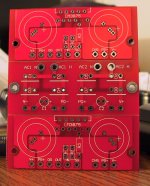
The signal ground goes back to the output ground through a small trace on the pcb. Here is a picture to show it. If the board is stuffed, it is hidden under R2.
--
Brian
breguetphile said:From pictures I wasn't able to see this, but as far as grounding is concerned, is the signal ground on the board tied to the channel ground on the board directly (if so, where, i can't see it).
Thanks!
The signal ground goes back to the output ground through a small trace on the pcb. Here is a picture to show it. If the board is stuffed, it is hidden under R2.
--
Brian
Attachments
A few measurements
I've made a few measurements on my amp that I thought I'd share. It's a dual mono layout using two Avel 160VA 18+18 transformers. One thing I had wondered about was the supply voltage drop at full power. With a measured 120v AC input, 20.4VAC output unloaded, here's what I get at the power input of the amp board:
+/- power supply voltage @ output power
26.66v @ 0w
25.4v @ 2.0w into 8 ohms
24.3v @ 24w into 8 ohms
23.5v @ 31.8w into 4 ohms
The last two readings were the maximum output just below clipping at 1kHz. Power was the same at 20kHz, but fell off at very low frequencies with 18.0w at 40Hz and 16.0w at 20Hz, both into 8 ohm loads. The clipping at low frequencies was not just flattened sine waves but odd looking behavior maybe due to output protection circuitry.
Frequency response at low power (less than 1w) was very wide, being less than 1dB down at 3Hz and 145kHz.
Thanks Brian, I guess I can now easily see it in the picture you posted. If possible, could you tell me the benefit of using such a small connection between the two grounds, or does it just not matter?
Amisdad, I'm glad someone finally noticed and responded to it. Alpha King is awesome, I wonder if its only popular here in the midwest.
Amisdad, I'm glad someone finally noticed and responded to it. Alpha King is awesome, I wonder if its only popular here in the midwest.
breguetphile said:Thanks Brian, I guess I can now easily see it in the picture you posted. If possible, could you tell me the benefit of using such a small connection between the two grounds, or does it just not matter?
Amisdad, I'm glad someone finally noticed and responded to it. Alpha King is awesome, I wonder if its only popular here in the midwest.
The goal of the small connection is the have a single path between the signal and output ground.
--
Brian
I have same problem as MATTYO5
The voltage between the outputs is 23 V on both cannels.
I can´t find a mistake in the circuit. I use the non insulated chip.
Has anyone an idea?
regards
Günter
The voltage between the outputs is 23 V on both cannels.
I can´t find a mistake in the circuit. I use the non insulated chip.
Has anyone an idea?
regards
Günter
I solved the problem.
I connected the PG with the SG. The DC-offset ist now by 72 and 63 mV.
The first impression of the sound is very good. For a comparison with my JLH, I give the GC 100 h because of the black gate I use.
regards
Günter
I connected the PG with the SG. The DC-offset ist now by 72 and 63 mV.
The first impression of the sound is very good. For a comparison with my JLH, I give the GC 100 h because of the black gate I use.
regards
Günter
Ok, the amp is basically finalized. 🙂 111mV offset on one channel and 34mv offset on the other...hmm. Anyway, sounds good...looks good. My dad and I worked for a couple weekends on it. Cool project. Now for some 4-8 channel versions 🙂 stay tuned!
-Matthew K. Olson
btw...i machined the aluminum volume knob this morning...my grandfather drilled the setscrew for it ... hmm...any resemblence to Peter's? 😉
-Matthew K. Olson
btw...i machined the aluminum volume knob this morning...my grandfather drilled the setscrew for it ... hmm...any resemblence to Peter's? 😉
Attachments
This is what I had done so far. .... It was like going to gym doing 25 sets of weight lifting when you make a square without the right power tools....T_T I want $$$.
Mattyo5 said:Ok, the amp is basically finalized. 🙂 111mV offset on one channel and 34mv offset on the other...hmm. Anyway, sounds good...looks good. My dad and I worked for a couple weekends on it. Cool project. Now for some 4-8 channel versions 🙂 stay tuned!
-Matthew K. Olson
btw...i machined the aluminum volume knob this morning...my grandfather drilled the setscrew for it ... hmm...any resemblence to Peter's? 😉
I like your amplifier. I really like the look of the knob with the non-beadblasted finish. It looks much more professional than the Indian ones that Peter posted pictures of.
I posted your 2 pictures in my gallery:
http://www.briangt.com/gallery/nigc
Feel free to send me a zip of pictures (800x600 resolution works best for me), and I will add more to my gallery.
--
Brian
S.C said:This is what I had done so far. .... It was like going to gym doing 25 sets of weight lifting when you make a square without the right power tools....T_T I want $$$.
LOL! that is so ugly it is cool 🙂
i especially like the in/out connectors pointing in random directions. its kind of like "ms paint picture" made to real life.I bet it Will sound so good that a new fad of "no parallel planes in amplifier sounds best!"
The fact is that my cuz didn't follow my instruction to drill thou that input holes, and the output holes is too small. I had only completed like 70% of the work. I am going to give this thing a few more ride to some shop, after that I'm gonna andoiz(spelling) it. Wait and see !😱
mines done by the way. it has 18 and 23 mv on the outs. it is in BrianGTs gallery.
http://www.briangt.com/gallery/nigc-neutron
I paralleled the 50k pots (from brigar electronics, via the post by variac on "cheap parts treasure hunt thread") they are actually 4x 50k audio taper so you can parallel them in pairs which will bring it closer to the ideal(25k close enough to 22k), and if one pot trace eventually becomes crappy then te other one in parallel will probably prevent major evil noises happening.
at first there was a tiny bit of buzz as i put my ear right next to the speaker, but i did not realize the boards are already "star grounded" (there is a tiny trace between signal ground and ground on the board) so i put a ground to the signal ground to my main ground. once i removed it it was fine. no buzz at all
I put capacitors on the input because this was supposed to work with some possibly untrustworthy sources. it is a "general purpouse" amp that may be connected to unreliable sources. i am working on a circuit to measure input DC and if zero then turn off
cap circuit with amercury wetted relay.
The sound of this amp is amazing for what an amp can do, i did not really believe an amp could make this much difference considering the amount of distortion a speaker creates compared even to a crappy amp.. it just makes you want to put on more and more different albums you may have "heard out" i especially enjoyed animals from pink floyd, but i had some Stella's by then 🙂
anyhow i will not use all those terms about sound-stage and so on but ill just say that it reminds me of the days when i was a kid and first hearing music on a decent system its like a whole nother listening experience up from what i have been "happy with" i have heard new sounds in albums i ave heard for 20 years! and to think i just built it for rear speakers for gaming 🙂!!!!
btw while experimenting with it i noticed that to my ears. a "full range" with questionable frequency response and so on sounds better to me than any multi driver speaker ihave (although EPI 201a is a great room filler). could be just me though 🙂 anyhow im gonna make some speakers with full range because of this minimalist approach..i like it 🙂
next week ill be taking it to my Friend who has a bryston(studio) and a mcintosh(upstairs) and see how it fares..he wants to sell his mc240 and may buy a 'clone from me if he likes it
back to construction
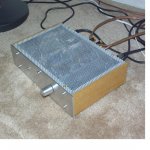
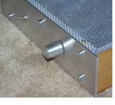
the power comes in the side so the power leads don't go near audio circuit (hint don't try and make a square hole in a heavy heatsink without a big milling machine PITA!!! it took longer almost than the whole rest of the project.)
I have a right angle power cable so you hardly notice it (in some pics there the receptacle i upside down and the lead faces forward..i sorted it)
I turned the knob from a piece of plexi and aluminum ring epoxied together. it took a while but unlike the square hole it was fun to do 🙂 also the part that attach's the rod to the pot was turned on the lathe (mini taig lathe). the rod itself was a titanium "skewer" from bicycle quick release.. i have many of these because i don't like them throwing out titanium bits at my weekend job (high end bike store) the knob interface to the front panel is a sealed bearing.
the inputs are twisted cat5e wire strands and much of the hookup is as well, the bigger bits are from an old cpu power supply, as is the power receptacle.
ins and out are mounted to a bit of 1/4 plexi which is in turn mounted to aluminum. the holes in the aluminum are big enough so the connectors are "self lit" from LEDs inside the case. it looks cool 🙂 and help if i have to change connections.
LEDs are powered from a separate small transformer (scavenged from a wall wart) with single diode rectifier + 1000 Uf cap and resistor (to give that nice gradual light and unlighting effect on turn off /on)
LEDs are 2 pieces amber "laserleds" made for case modders and motorbike customizers they are supposed to run 12v but i run em 9v they just point up inside the case and the reflection inside take care of the "look"
caution! post made after consuming "Slella Artois" please direct complaints to
http://www.stellaartois.ca/
http://www.briangt.com/gallery/nigc-neutron
I paralleled the 50k pots (from brigar electronics, via the post by variac on "cheap parts treasure hunt thread") they are actually 4x 50k audio taper so you can parallel them in pairs which will bring it closer to the ideal(25k close enough to 22k), and if one pot trace eventually becomes crappy then te other one in parallel will probably prevent major evil noises happening.
at first there was a tiny bit of buzz as i put my ear right next to the speaker, but i did not realize the boards are already "star grounded" (there is a tiny trace between signal ground and ground on the board) so i put a ground to the signal ground to my main ground. once i removed it it was fine. no buzz at all
I put capacitors on the input because this was supposed to work with some possibly untrustworthy sources. it is a "general purpouse" amp that may be connected to unreliable sources. i am working on a circuit to measure input DC and if zero then turn off
cap circuit with amercury wetted relay.
The sound of this amp is amazing for what an amp can do, i did not really believe an amp could make this much difference considering the amount of distortion a speaker creates compared even to a crappy amp.. it just makes you want to put on more and more different albums you may have "heard out" i especially enjoyed animals from pink floyd, but i had some Stella's by then 🙂
anyhow i will not use all those terms about sound-stage and so on but ill just say that it reminds me of the days when i was a kid and first hearing music on a decent system its like a whole nother listening experience up from what i have been "happy with" i have heard new sounds in albums i ave heard for 20 years! and to think i just built it for rear speakers for gaming 🙂!!!!
btw while experimenting with it i noticed that to my ears. a "full range" with questionable frequency response and so on sounds better to me than any multi driver speaker ihave (although EPI 201a is a great room filler). could be just me though 🙂 anyhow im gonna make some speakers with full range because of this minimalist approach..i like it 🙂
next week ill be taking it to my Friend who has a bryston(studio) and a mcintosh(upstairs) and see how it fares..he wants to sell his mc240 and may buy a 'clone from me if he likes it
back to construction
the power comes in the side so the power leads don't go near audio circuit (hint don't try and make a square hole in a heavy heatsink without a big milling machine PITA!!! it took longer almost than the whole rest of the project.)
I have a right angle power cable so you hardly notice it (in some pics there the receptacle i upside down and the lead faces forward..i sorted it)
I turned the knob from a piece of plexi and aluminum ring epoxied together. it took a while but unlike the square hole it was fun to do 🙂 also the part that attach's the rod to the pot was turned on the lathe (mini taig lathe). the rod itself was a titanium "skewer" from bicycle quick release.. i have many of these because i don't like them throwing out titanium bits at my weekend job (high end bike store) the knob interface to the front panel is a sealed bearing.
the inputs are twisted cat5e wire strands and much of the hookup is as well, the bigger bits are from an old cpu power supply, as is the power receptacle.
ins and out are mounted to a bit of 1/4 plexi which is in turn mounted to aluminum. the holes in the aluminum are big enough so the connectors are "self lit" from LEDs inside the case. it looks cool 🙂 and help if i have to change connections.
LEDs are powered from a separate small transformer (scavenged from a wall wart) with single diode rectifier + 1000 Uf cap and resistor (to give that nice gradual light and unlighting effect on turn off /on)
LEDs are 2 pieces amber "laserleds" made for case modders and motorbike customizers they are supposed to run 12v but i run em 9v they just point up inside the case and the reflection inside take care of the "look"
caution! post made after consuming "Slella Artois" please direct complaints to
http://www.stellaartois.ca/
neutron7 said:LEDs are powered from a separate small transformer (scavenged from a wall wart) with single diode rectifier + 1000 Uf cap and resistor (to give that nice gradual light and unlighting effect on turn off /on)
LEDs are 2 pieces amber "laserleds" made for case modders and motorbike customizers they are supposed to run 12v but i run em 9v they just point up inside the case and the reflection inside take care of the "look"
I am thinking about put one/two blue led inside, and made the gap blue... It will looks cool/cold, but it will be annoying while I'm watching movies with leds off.....except those blue light from the amp
😕
- Status
- Not open for further replies.
- Home
- Amplifiers
- Chip Amps
- Gainclone building thread based on BrianGT's boards