thanks for the info, looks like I will have to fire up the dremel then.chipco3434 said:Yes. Anodized coatings are insulators. Not great because the slightest scratch goes through the coating, but still an insulator.
Also what is the size of the hole in the 3875 chip? I need to know what size the tap bit should be.
AJ Bertelson said:Does anodizing affect metal the same way paint does? Do I have to sand away until I get bare metal to ground my plug?
Anodizing puts a aluminum oxide layer over the aluminum, which is the same material as the insulators that I sent out with the kits, but in a much thinner form, which could cause you problems if you accidently scratch it during mounting.
--
Brian
AJ Bertelson said:thanks for the info, looks like I will have to fire up the dremel then.
Also what is the size of the hole in the 3875 chip? I need to know what size the tap bit should be.
I used a #4 tap for mounting the gainclone with the insulated package and rubber bushing. If you are using the non-insulated version, a #6 screw will work.
--
Brian
Got a bit accomplished today.
got my two parmetal cases, only took them 3 weeks to get it to me. Working with the one on the right now.
All the holes are drilled out and components installed. Until I realized I didn't have a screw for my ground.
First channel soldered up.
Tomorrow I will get the ground worked out and fire it up.
got my two parmetal cases, only took them 3 weeks to get it to me. Working with the one on the right now.
An externally hosted image should be here but it was not working when we last tested it.
All the holes are drilled out and components installed. Until I realized I didn't have a screw for my ground.
An externally hosted image should be here but it was not working when we last tested it.
First channel soldered up.
An externally hosted image should be here but it was not working when we last tested it.
Tomorrow I will get the ground worked out and fire it up.
Nice setup, but one question. Is there a reason the one output board is not setup so the heat sink is over the vent holes in the base of the chassis?
Hi Wardsweb,
I'm going to tell Doc. B. and the whole bottlehead gang that you are going to build something SS!!!
Heresy!!😉
Cheers,
Bas
I'm going to tell Doc. B. and the whole bottlehead gang that you are going to build something SS!!!
Heresy!!😉
Cheers,
Bas
Strong, the Dark Side is. 😉
Bas Horneman said:Hi Wardsweb,
I'm going to tell Doc. B. and the whole bottlehead gang that you are going to build something SS!!!
Heresy!!😉
Cheers,
Bas
hmm, didn't even notice that. I figured I would run it it without the case on the top for a couple of days and see what happens.Wardsweb said:Nice setup, but one question. Is there a reason the one output board is not setup so the heat sink is over the vent holes in the base of the chassis?
Oh BTW, the devil is in the details. I order a 3-prong plug from oselectronics. Came with the prongs to plug into the power strip but it didn't have the plug to plug into the amp.
 You guys break me up.
 FYI: I"ve only been into tubes a little over one year. I've been into SS for 25 years.
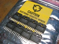
Heatsink for brians gainclone
found some surplus heatsinks in Intel retail plastic packageing they look like they would be for P4 CPU'S they have a aluminum Base which has diminsions of 90mm(3 1/2") X63mm(2 1/2") the fins appear to be thin plates of 5 aluminum then 20 copper then 5 aluminum the fins stand up 40mm tall off the base at the fin juncture at the base with furrows and the fins appear to be pressed fit to the heatsink base they weigh more then a pound.I think these could be used anyones thought's
found some surplus heatsinks in Intel retail plastic packageing they look like they would be for P4 CPU'S they have a aluminum Base which has diminsions of 90mm(3 1/2") X63mm(2 1/2") the fins appear to be thin plates of 5 aluminum then 20 copper then 5 aluminum the fins stand up 40mm tall off the base at the fin juncture at the base with furrows and the fins appear to be pressed fit to the heatsink base they weigh more then a pound.I think these could be used
anyones thought'sMonster Clone
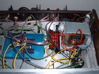
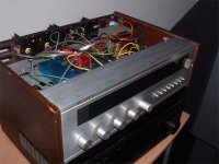
For cost and convenience, I used a spare transformer I had lying around that came out of an old (circa 1980) yamaha amplifier. It had what I could best describe as two center taps on a single secondary. One set of wires measured 18-0-18, and the other 36-0-36. Since the latter was way too high, I opted to use the 18-0-18 tap for about ±22V rails and roughly 20Wrms output power. Just for the heck of it, I also threw in two 10000uF caps from the same yamaha amp. It sounded good, but I seemed to have a little bit of distortion during transients, which I attributed to clipping, given the high gain, low rail voltages, and >1Vrms output of my old CD player. So, today I decided to crank things up a bit.
I connected the 36-0-36 CT wires to the rectifier board, which resulted in ±48V rails. A quick test showed that the output voltage into an 8-ohm load to be 25VRMS with a 1kHz sine wave, slightly below clipping. Thus, my amp went from 20WRMS to just under 80. Next came a listening test. The transients sounded much better, and the bass was noticably more forceful, and also more responsive. Turning the volume control to maximum (which required me to cover my ears), I could still detect no clipping or other objectional sound being created by the amplifier. Of course, this is with very crappy pioneer speakers, but I'd say it sounded about as good as one could expect from these speakers. With the large PII heatsink I'm using to cool the chips, they get only slightly warm to the touch at moderate volume levels. I don't know what effect the increased voltage will have on the longevity of my chips, but the results seem to be quite pleasing.
I guess I should include a disclaimer: You are responsible for anything you do to your own amplifier. If you choose to run your chip amp at higher than the rated voltage, you may be risking your amps and/or speakers. I have not tested the chips with a <8Ohm load, so I don't know if it is safe. Etc., Etc.
So far, my experience with stepping up the voltage a bit has been a good one, and It seems that the LM3875 can happily operate with up to a 2x35V transformer. Naturally, I might post next week saying I smoked the chips, but I think they'll be ok. Anyway, I think I'll rate this modification "two evil grins" . Oh, and of course, a couple pictures...
The chassis is from an ancient scott stereo I gutted.
For cost and convenience, I used a spare transformer I had lying around that came out of an old (circa 1980) yamaha amplifier. It had what I could best describe as two center taps on a single secondary. One set of wires measured 18-0-18, and the other 36-0-36. Since the latter was way too high, I opted to use the 18-0-18 tap for about ±22V rails and roughly 20Wrms output power. Just for the heck of it, I also threw in two 10000uF caps from the same yamaha amp. It sounded good, but I seemed to have a little bit of distortion during transients, which I attributed to clipping, given the high gain, low rail voltages, and >1Vrms output of my old CD player. So, today I decided to crank things up a bit.
I connected the 36-0-36 CT wires to the rectifier board, which resulted in ±48V rails. A quick test showed that the output voltage into an 8-ohm load to be 25VRMS with a 1kHz sine wave, slightly below clipping. Thus, my amp went from 20WRMS to just under 80. Next came a listening test. The transients sounded much better, and the bass was noticably more forceful, and also more responsive. Turning the volume control to maximum (which required me to cover my ears), I could still detect no clipping or other objectional sound being created by the amplifier. Of course, this is with very crappy pioneer speakers, but I'd say it sounded about as good as one could expect from these speakers. With the large PII heatsink I'm using to cool the chips, they get only slightly warm to the touch at moderate volume levels. I don't know what effect the increased voltage will have on the longevity of my chips, but the results seem to be quite pleasing.
I guess I should include a disclaimer: You are responsible for anything you do to your own amplifier. If you choose to run your chip amp at higher than the rated voltage, you may be risking your amps and/or speakers. I have not tested the chips with a <8Ohm load, so I don't know if it is safe. Etc., Etc.
So far, my experience with stepping up the voltage a bit has been a good one, and It seems that the LM3875 can happily operate with up to a 2x35V transformer. Naturally, I might post next week saying I smoked the chips, but I think they'll be ok. Anyway, I think I'll rate this modification "two evil grins"
. Oh, and of course, a couple pictures...The chassis is from an ancient scott stereo I gutted.
Attachments
I guess I should include a disclaimer: You are responsible for anything you do to your own amplifier. If you choose to run your chip amp at higher than the rated voltage, you may be risking your amps and/or speakers. I have not tested the chips with a <8Ohm load, so I don't know if it is safe. Etc., Etc.
I could drive 120 km/h in the center of city today without accidents ( don't know about tomorrow ). I could have used another example:
http://timesofindia.indiatimes.com/articleshow/620331.cms
This kind of overvoltage advice is potentially dangerous, plain unsafe and not recommended for those that want a healthy amp on the long run and unburnt speakers. This practice is not the same as overclocking CPU's as I've understood some think it's in the same league.
Better use a LM3886 if you want more power. One burnt speaker costs far more than 2 pieces LM3886.
This kind of info is actually very useful. If you don't mind experimenting and putting in danger your system, we would be glad to hear about long time performance in a future😉
Hi Peter, please bear in mind that the PCB's are also bought by a number of starters that may not see the risk in doing this. They probably read this thread too and may be tempted by successful stories to push devices over their maximum limits. They could have less success in doing so, ending up with damage blaming anyone but themselves. This project is a tempting one for new DIYers also because it is almost a guarantee to a good working good sounding amp. This advice could compromise that goal.
If one persists in challenging the manufacturers absolute maximum limits I would strongly advice in using a speaker protection circuit and secondly to never leave the amp on while one is away from home.
What do the forum rules say about unsafe advice ?
If one persists in challenging the manufacturers absolute maximum limits I would strongly advice in using a speaker protection circuit and secondly to never leave the amp on while one is away from home.
What do the forum rules say about unsafe advice ?
It's not advice. It's an information that can be useful to some and dangerous to others, right? You Europeans are so sensitive about safety.😉
I'm glad I'm living in America😉
I'm glad I'm living in America😉
I don't see the point in taking unneccessary risks and I can't imagine why one would exceed limits for 1 % better sound and don't know the final outcome. Those guys and gals at National Semiconductor don't test maximum limits for their devices just because they've nothing better to do.
Recently I visited a friend and suddenly we heard sirenes. It turned out to be a neighbour that had fiddled/DIYed in his main power outlet ( forbidden BTW ) with a dubious surge switch causing his house to burn. In Europe it is quite common that houses are built in a row. Now suppose noone had called in time, there were children sleeping in the house next to the one that burnt. That's why safety is of primary importance here ( in general ) as we live in a densily populated area. If it's not you that's harmed it can be another person that suffers from your unresponsible behaviour ( speaking in general ! ).
We europeans probably do the same experimenting but we would first test it thoroughly over some time, document it and then publish the results after a success rate is proven 😉
Compare it to the question of genetic modification of soya if you like, that's why I am glad to live in Europe.
- Status
- Not open for further replies.
- Home
- Amplifiers
- Chip Amps
- Gainclone building thread based on BrianGT's boards