I figured out my -30vdc on the speaker outputs. It was a short, though not easy to find. I'm using BC 1% resistors for the 22k feedback resistors, and because they have to be so close physically to the chip, if something goes wrong with them, they can short something out. Anyway, turns out a little of the paint? had chipped off the resistor exposing the endcap (under the resistor...i couldn't see the paint chip unless i unsoldered the resistor) and bridging pin 3 (speaker out) to pin 4 (- rail). So, that was my problem. Also, now i have 110mV dc offset on one channel and 40mv on the other. Doesn't seem to make much difference, both channels are silent as long as I ground the chassis. Later!
-Matthew K. Olson
-Matthew K. Olson
Jamh said:As promised, here's the picture. One cool feature, the case is made of aluminum L shape sections you can buy anywhere.
Jam,
I added your pictures to my gallery in the same album as the pictures of your first gainclone.
http://www.briangt.com/gallery/nigc-jam-h
Main NIGC project gallery page:
http://www.briangt.com/gallery/nigc
I will start mailing out the free pcb sets soon to those who have submitted entries.
--
Brian
BrianGT said:
Jam,
I added your pictures to my gallery in the same album as the pictures of your first gainclone.
http://www.briangt.com/gallery/nigc-jam-h
Main NIGC project gallery page:
http://www.briangt.com/gallery/nigc
I will start mailing out the free pcb sets soon to those who have submitted entries.
--
Brian
Brian,
If you don't mind I would rather you hold on to mine and send it together with my order in the phase II group buy. I am yet to decide on the quantity.
Chris
chris ma said:
Brian,
If you don't mind I would rather you hold on to mine and send it together with my order in the phase II group buy. I am yet to decide on the quantity.
Chris
Sounds good. I can do that.
--
Brian
Brian,
That is Jmah's gainclone you have posted on your website, I would like to take credit but unfotunately my work is not as good.........😉
That is Jmah's gainclone you have posted on your website, I would like to take credit but unfotunately my work is not as good.........😉
jam said:Brian,
That is Jmah's gainclone you have posted on your website, I would like to take credit but unfotunately my work is not as good.........😉
heh.. He is also Jam, with the H being the first letter of his last name. It is not meant to refer to you. I changed the gallery title to Jam H, as to not cause confusion.
--
Brian
finally got my camera back
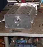
a few pictures of my clone. And yes, i have reused the case (since i blew up the left channel some time ago i figured, hey, let's just get the old thing out and replace it with brian's boards).
I'll post some pics of a completely new one tomorrow (if i can get it back from the guy i lent it to).
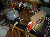
second picture features my "passive shunt mode pre" (ahem 😉 ) which is hellish thing. For some reason (everything's grounded properly now) if I connect it to my amp, i've got radio again. If i don;t, it's dead quiet. Strange.
Brian, if you want i can email you some larger (and better quality) versions.
a few pictures of my clone. And yes, i have reused the case (since i blew up the left channel some time ago i figured, hey, let's just get the old thing out and replace it with brian's boards).
I'll post some pics of a completely new one tomorrow (if i can get it back from the guy i lent it to).
second picture features my "passive shunt mode pre" (ahem 😉 ) which is hellish thing. For some reason (everything's grounded properly now) if I connect it to my amp, i've got radio again. If i don;t, it's dead quiet. Strange.
An externally hosted image should be here but it was not working when we last tested it.
An externally hosted image should be here but it was not working when we last tested it.
An externally hosted image should be here but it was not working when we last tested it.
An externally hosted image should be here but it was not working when we last tested it.
An externally hosted image should be here but it was not working when we last tested it.
An externally hosted image should be here but it was not working when we last tested it.
Brian, if you want i can email you some larger (and better quality) versions.
Re: finally got my camera back
Looks good! Drop me an e-mail with a zip of all the pictures (higher quality is good), and I will put them in my gallery.
--
Brian
matjans said:Brian, if you want i can email you some larger (and better quality) versions.
Looks good! Drop me an e-mail with a zip of all the pictures (higher quality is good), and I will put them in my gallery.
--
Brian
sorry guys, last one !
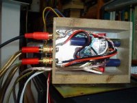
A second brianGT kit based gainclone. This one features an active opa627/buf634 based pre, alps volume pot. It's fully BS proof: all silver wiring, teflon insulation etc.
The shop I went to for wood didn;t have the same stuff as last time so i just took 4cm thick multiplex (which i intend to replace with the real stuff later). Have to fix some rf shielding too. Maybe I'll use some copper foil.
An externally hosted image should be here but it was not working when we last tested it.
An externally hosted image should be here but it was not working when we last tested it.
An externally hosted image should be here but it was not working when we last tested it.
An externally hosted image should be here but it was not working when we last tested it.
An externally hosted image should be here but it was not working when we last tested it.
An externally hosted image should be here but it was not working when we last tested it.
nice work matjans
Looks oke to me!
Can you post the schematics of the preamp/buffer? As well as inner interconnections and your earthing scheme?
Thank you
E&E
Looks oke to me!
Can you post the schematics of the preamp/buffer? As well as inner interconnections and your earthing scheme?
Thank you
E&E
the schematics are to be found somewhere in this diyaudio thread
Most of the resistors went to the underside of the pcb. I've left out the small output resistors as i couldn;t get it into oscillating so i thought what the heck. Let's at least in part adhere to the 'less is more' slogan.
Most of the resistors went to the underside of the pcb. I've left out the small output resistors as i couldn;t get it into oscillating so i thought what the heck. Let's at least in part adhere to the 'less is more' slogan.
ok, here you go.
oh yeah and i connected a 200pF capacitor across the inputs (directly on the board) to prevent some hf entering the amp.
An externally hosted image should be here but it was not working when we last tested it.
oh yeah and i connected a 200pF capacitor across the inputs (directly on the board) to prevent some hf entering the amp.
PMeade said:Exactly how do you measure DC offset?---Thanks
Paul
Oh me..let me try to answer this one. You put the RED probe of the multi-meter connect to the +ve speaker binding post of your amp. You put the black probe to the -ve speaker binding post. Set the mutimeter to measure DC before apply power to the amp. Do not connect speaker to your binding posts unless you are certain the DC offset is less than 900mV or so.
Hope this help,
Chris
PMeade said:Thank you much. So 70.7 mv is ok then.
Paul
Yes, that is just fine, and there should be no noticable thump when you turn on the amp.
- Status
- Not open for further replies.
- Home
- Amplifiers
- Chip Amps
- Gainclone building thread based on BrianGT's boards