Pictures. I'm building this amp in an enclosure I found in an electronics surplus store. It housed some kind of test/measurements gear, I have no idea what it was. The size looked right, and this way I got a power switch, IEC connector and fuse holder for free, all of them already wired up.
This is what the front looks like, I'm leaving this unchanged. I'll probably use 2 of the LEDs to indicate power for each rail.
The new back panel, with RCA connectors and binding posts added. You can see all the holes from the DB25 and other connectors I had to remove. This'll impact shielding, but I haven't had much of an RFI problem in my setup except with my phono stage, so I'm hoping it won't make a difference. On the plus side, this means free ventilation 🙂
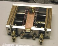
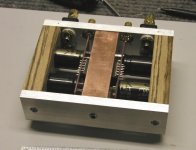
The enclosure with the transformer. The PCBs will be a tight squeeze in there, and I might get some hum pickup. We'll see. If it doesn't work out, I'll buy an enclosure from Hammond or Par Metal or something.
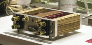
And pictures of what the completed amp will look like. Once I'm done, I'll try and find wood strips to put in those side channels. They originally had plastic inserts, but one of those was gone.
This is what the front looks like, I'm leaving this unchanged. I'll probably use 2 of the LEDs to indicate power for each rail.
An externally hosted image should be here but it was not working when we last tested it.
The new back panel, with RCA connectors and binding posts added. You can see all the holes from the DB25 and other connectors I had to remove. This'll impact shielding, but I haven't had much of an RFI problem in my setup except with my phono stage, so I'm hoping it won't make a difference. On the plus side, this means free ventilation 🙂
An externally hosted image should be here but it was not working when we last tested it.
The enclosure with the transformer. The PCBs will be a tight squeeze in there, and I might get some hum pickup. We'll see. If it doesn't work out, I'll buy an enclosure from Hammond or Par Metal or something.
An externally hosted image should be here but it was not working when we last tested it.
And pictures of what the completed amp will look like. Once I'm done, I'll try and find wood strips to put in those side channels. They originally had plastic inserts, but one of those was gone.
An externally hosted image should be here but it was not working when we last tested it.
An externally hosted image should be here but it was not working when we last tested it.
Souuld be fine, but I got the 330VA model for only $5 more. I'll admit that my attitude can get me in a lot of trouble though! A few bucks here and there.....
But that's with an external power supply, right? Mine might be the smallest one-box GC around 🙂 Of course, that won't be a good thing if it hums or has other problems.
That's a beautiful amp.
Variac, the 330VA toroid would have been an even tighter fit inside that chassis. Size was one of the reasons I decided to go with the 250VA one.
That's a beautiful amp.
Variac, the 330VA toroid would have been an even tighter fit inside that chassis. Size was one of the reasons I decided to go with the 250VA one.
That's a mighty small amp! damn you peter 😉 you'll probably never stop to amaze us. (but skipping a party ?  )
)
How are you going to fasten the lm's to the heatsink? seams like hell of a job...
I'm still waiting for my boards. This time i think i'll build an integrated, opa627/buf634 buffered amp with a source switch. I'm even thinking about including the psu in the amp itself.
longer time listening has learned me that i like a gc better with a buffered pre. Just adds that little 'kick'.
ciao,
/matti
)How are you going to fasten the lm's to the heatsink? seams like hell of a job...
I'm still waiting for my boards. This time i think i'll build an integrated, opa627/buf634 buffered amp with a source switch. I'm even thinking about including the psu in the amp itself.
longer time listening has learned me that i like a gc better with a buffered pre. Just adds that little 'kick'.
ciao,
/matti
In that arrangement, the chip has to be mounted first, and then PCB soldered on top of it. In case of chip failure, it has to be desoldered first (to remove it). I'm not concerned with that, as I didn't experience a failure yet (in any of my amps). I once had a short on the output for more than an hour and nothing happend (but it got pretty hot).
I also like GC better with a buffer, but I'm using TVX stage, which seems to be a good combination of both (volume control and a buffer).
I also like GC better with a buffer, but I'm using TVX stage, which seems to be a good combination of both (volume control and a buffer).
Saurav said:But that's with an external power supply, right?
It is with external supply, but I think I'll use batteries for that.
Your case looks pretty nice too, very clean and elegant. I don't think you'll be getting hum. Those chips are pretty resistant to transformer interferences (but not to improper grounding).
Peter,
Have you ever thought about making a 5 or 6 channel amp for
surround sound? Since my HT Receiver bit the dust i've been
thinking of 5 channels of GC and a HT Processor...
I know it's not purist stereo, but i'd like to see what you came up with!
m. (can't wait to put together the new GC kits!)
Have you ever thought about making a 5 or 6 channel amp for
surround sound? Since my HT Receiver bit the dust i've been
thinking of 5 channels of GC and a HT Processor...
I know it's not purist stereo, but i'd like to see what you came up with!
m. (can't wait to put together the new GC kits!)
Adding to Moe's coments:
I just bought a Philips multi channel SACD,DVD,CD changer 795 SA
Amazing, considering it's price is about $260.
I got mine for $110 because it was an out of box shelf demo.
Get this- it upsamples Cd's!! How does it sound? well I'm running it through my TV speakers- all my systems are being worked on.
Anyway, it has 6 audio outputs-and Dolby and DTS .
Does this mean I can just run the output through 6 gainclones with vol. controls? why do people have HT receivers? I guess for broadcast? Anyway I'm excited and confused..kinda fun.....
Your case looks pretty nice too, very clean and elegant.
OK, now you're just being nice. I've seen the kind of work you do, and I know what your standards of 'clean and elegant' are 🙂 Thanks for the compliment.
I don't think you'll be getting hum. Those chips are pretty resistant to transformer interferences (but not to improper grounding).
Thanks for the tip. I moved the transformer over to one of the front corners, so I'll have more space in the opposite rear corner to mount the PCBs. With the transformer in the middle, I was just short on both sides. Keeping all the audio components on one side means longer wiring, but it also means I can route the power supply wiring on the other side of the chassis.
I should be putting everything together tomorrow. What's a basic set of power-on tests for this? I can think of a few obvious ones - test the power supply first for correct voltages. Disconnect, leave the voltmeter connected (or use a bleeder resistor) and let the caps discharge (I have the 4.7uF caps on the PSU board installed). Connect power supply to audio PCBs. Put a 10 ohm power resistor across the speaker binding posts. Check voltages on power supply pins, check for DC on the output.
Anything else?
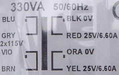
I received my Avel transformer from Parts Express and I'd like to connect it without blowing up my pcb or electrocuting myself. I am using a 3-prong, male ac receptacle and I don't understand how to wire up the four primaries. The picture below is the diagram from the transformer.
widman
widman
Attachments
widman said:I received my Avel transformer from Parts Express and I'd like to connect it without blowing up my pcb or electrocuting myself. I am using a 3-prong, male ac receptacle and I don't understand how to wire up the four primaries. The picture below is the diagram from the transformer.
widman
Since you are located in the US, you will want to wire both pairs of primaries in parallel with each other, meaning that the blue and violet wires will be tied together and the brown and grey wires will be tied together.
The part of the primary labeled with the dot usually indicates the side that should be tied to the AC(hot) line.
Very Important:
Make sure to have a power supply fuse (2A slowblo should work) in series with the AC(hot) line going into the transformer.
For 240vac operation, you would want to wire the primaries in series.
--
Brian
Brian,
What are you doing answering e-mail and checking the forum This early on your 1st morning as Mr. Meredith?
Lee
What are you doing answering e-mail and checking the forum This early on your 1st morning as Mr. Meredith?
Lee
jean-paul said:Hi Peter, what is the transformer you use ? With 35 V BG's it can't be 2 x 22 V, can it ?
2 x 22V, 400VA Plitron produces 34V on rails. Theoretically it should be fine, but I don't want to push it that far. I'll be using batteries (as I have a lot of them) for 24V rails.
Peter Daniel said:
2 x 22V, 400VA Plitron produces 34V on rails.
I thouight VAC * 1.414 = VDC (22 * 1.414 = 31)?
Or, as usual, am I simply confused...
- Status
- Not open for further replies.
- Home
- Amplifiers
- Chip Amps
- Gainclone building thread based on BrianGT's boards