This thing still going on or no? Can we extend it? I just need 2 or 3 more days till I get mine pretty much done 🙂
ble0t said:This thing still going on or no? Can we extend it? I just need 2 or 3 more days till I get mine pretty much done 🙂
Yes, it is.
For those who have sent me pictures, which are in my gallery, and haven't received their free pcb set, drop me an e-mail to: brian-orders@darg.net with the subject "Contest PCB" along with your address. I have a hard time associating the user names with the address information in my database.
I have a stack of pcbs waiting to go out.
--
Brian
Rail E at output
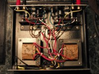
Sorry for the delay, I have been busy. Here's a pic of my first attempt at a non-inverted gain clone(NIGC). Since it shows only negative supply rail at the outputs, it's a non-working, non-inverted gain clone (NWNIGC) Any suggestions appreciated.
Thanks in Advance
Jimbo
Sorry for the delay, I have been busy. Here's a pic of my first attempt at a non-inverted gain clone(NIGC). Since it shows only negative supply rail at the outputs, it's a non-working, non-inverted gain clone (NWNIGC)
Any suggestions appreciated.Thanks in Advance
Jimbo
Attachments
- supply at both outputs or just one? i had a resistor that lost some paint and became conductive between pin 3 and 4....speaker out and - rail. 🙁 did you check power from the power supply to make sure the + and - rails were there?
-Matthew K. Olson
-Matthew K. Olson
Re: Rail E at output
Since you are using a normal bridge rectifier, and not the dual bridge setup, you should only have 1 gnd wire going to the pcb from your transformer center-tap/chassis gnd.
Here is an alternate setup for you to try:
----------------------------------------
IN/SGND - to rca
OUT/OG - to binding posts
+V/-V - to power supply rails
CHG - chassis gnd, tie this to your central ground
That should be all that you need to use, with the rest of your grounds from your transformer, and AC GND going to a central ground in your case.
Give that a try. I suspect that you might have a gnd loop now, or something strange going on.
--
Brian
jimbo149 said:Sorry for the delay, I have been busy. Here's a pic of my first attempt at a non-inverted gain clone(NIGC). Since it shows only negative supply rail at the outputs, it's a non-working, non-inverted gain clone (NWNIGC)
Thanks in Advance
Jimbo
Since you are using a normal bridge rectifier, and not the dual bridge setup, you should only have 1 gnd wire going to the pcb from your transformer center-tap/chassis gnd.
Here is an alternate setup for you to try:
----------------------------------------
IN/SGND - to rca
OUT/OG - to binding posts
+V/-V - to power supply rails
CHG - chassis gnd, tie this to your central ground
That should be all that you need to use, with the rest of your grounds from your transformer, and AC GND going to a central ground in your case.
Give that a try. I suspect that you might have a gnd loop now, or something strange going on.
--
Brian

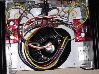
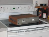
A bit of an overkill with those heatsinks, but very original and interesting approach with a pot. Nicely done.
Looks good, well done. But put some sleeving over those exposed mains connections for safety's sake! 😉
bit of an overkill with those heatsinks
Agreed, but the price was right ~ FREE. Cut in half they were two small, i.e., not tall enough. Anyway, I have a little honey pot of heatsinks in a stash. You'll be seeing those again.
sleeving over those exposed mains connections for safety's sake!
The only exposed items are the bottom of the fuse connector and the solder joints on the DPDT switch. Otherwise, all covered.
The pot arrived without the requisite unobtainium 9MM x .7??? nut. So thus and so, find an alternative. I will be attaching a knob/rod/silastic tube to the pot shaft that will pass through the oilite bush on the front panel.
Rail E at outputs
Still showing PS rail -E at both outputs with only one V ground from each board. I tried the RCA and binding post grounds in both floating and chassis configurations; makes no difference. Still -22V at outputs. Any new ideas?
Jimbo
Still showing PS rail -E at both outputs with only one V ground from each board. I tried the RCA and binding post grounds in both floating and chassis configurations; makes no difference. Still -22V at outputs. Any new ideas?
Jimbo
Any chance at all that a solder joint is touching an adjacent pad? Or possibly a very small piece of wire or component lead doing the same? Check around the chip joints as that is where things are closest together.
Just a thought.
Just a thought.
Everything checks out perfectly; no bridges, cold joints, all component values correct and in the correct holes, PS voltages correct. Still -22V at outputs. I tired of the project and scrapped the boards this afternoon. I'll try again with no boards next time, the transformers and bridges work just fine.
Jimbo
Jimbo
Re: Re: Rail E at output
Jimbo, sorry to hear about your problem.
Did you try Brain's suggestions? From you picture you have the CHG to your RCA input ground that may cause you problems..
Chris
Or have you try doing one channel only first? Try one transformer, one bridge rectifier and one BrainGT board to see if you have problems?
BrianGT said:
Here is an alternate setup for you to try:
----------------------------------------
CHG - chassis gnd, tie this to your central ground
That should be all that you need to use, with the rest of your grounds from your transformer, and AC GND going to a central ground in your case.
Give that a try. I suspect that you might have a gnd loop now, or something strange going on.
--
Brian
Jimbo, sorry to hear about your problem.
Did you try Brain's suggestions? From you picture you have the CHG to your RCA input ground that may cause you problems..
Chris
Or have you try doing one channel only first? Try one transformer, one bridge rectifier and one BrainGT board to see if you have problems?
I made a bit pof a marathon of it on Sunday, trying every possible way to ground the boards, starting with Brian's suggestions; even RCA grounds lifted. The result was unwavering -22V at output. Each channel is(was) powered by its own seperate xformer and bridge.
Jimbo
Jimbo
Jimbo
It may be a good try just start to disconnect (electrically) one channel completely. Just try out power only one channel first and fix any problem if there is any. Then try the other channel on its own. At least you have a isolated scope of problems to solve.
Chris
It may be a good try just start to disconnect (electrically) one channel completely. Just try out power only one channel first and fix any problem if there is any. Then try the other channel on its own. At least you have a isolated scope of problems to solve.
Chris

- Status
- Not open for further replies.
- Home
- Amplifiers
- Chip Amps
- Gainclone building contest details (from BrianGT group order)