Just to illustrate 2 scenarios with 4,700uF and 10,000uF with 4ohm load (speaker impedance matters) and transformer with 0.3ohm coil resistance (I just simulate the positve rail).
You get around 1V more usable from the power supply with 10,000uF. Going beyond 10,000uF will not make much difference regarding ripple.
This is for continuous operation. I'll simulate the burst.


You get around 1V more usable from the power supply with 10,000uF. Going beyond 10,000uF will not make much difference regarding ripple.
This is for continuous operation. I'll simulate the burst.

Always include output protection (load disconnect) in designs. Failing that you can either crowbar the speaker output, or shut down he power supply having limited energy (like Carver).
Supply capacitance is way overrated. Beyond a certain level it is more than wasted, you also decrease the conduction angle on the diodes. Higher peak currents and more HF content on ripple. Overall a total waste. If a couple volts makes any difference, you are clipping and needed a larger amp anyway.
People latch onto the smallest detail without considering the larger picture.
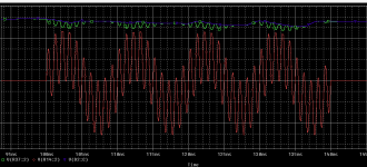
In this example, with 20ms burst, 4,700uF output sine wave peak clips, but with 10,000uF it is still ok.
4,700uF can hold up to 10ms burst.
In RED the output sine wave and in green the positive PS rail.
In real music, we need longer bursts (>100ms) so, I don't think it's worth to add much more than 4,700uF or 10,000uF for 4ohm per channel to get this extra dynamic power - I'd satistfy myself with continuous power and with 1 to 2V peak to peak ripple as we get with these capacitances.
It's a matter of designing to achieve your goals.
Sure, okay. Now what is the difference in power, and at what power level?
Like I said, in real music if you are that close, you are probably clipping. Given the speaker distortion, momentary clipping is probably not noticable if the amplifier is designed well. Much concern over something that doesn't matter in a practical sense. If you run that close, you need a larger amplifier.
Like I said, in real music if you are that close, you are probably clipping. Given the speaker distortion, momentary clipping is probably not noticable if the amplifier is designed well. Much concern over something that doesn't matter in a practical sense. If you run that close, you need a larger amplifier.
Very little and with very short burst. Not worth - I agree with you.
This was just to illustrate what I wrote before.
As I shown, you get only 1V more going from 4,700uF (83W) to 10,000uF (89W),
83 to 89W = 0.6dB.
I listen to music using up to 10W maximum (<90dB SPL since I don't like loud) and my amp is rated at 80W - this is the way to go!
This was just to illustrate what I wrote before.
As I shown, you get only 1V more going from 4,700uF (83W) to 10,000uF (89W),
83 to 89W = 0.6dB.
I listen to music using up to 10W maximum (<90dB SPL since I don't like loud) and my amp is rated at 80W - this is the way to go!
Peak to average levels vary with source material. This can range from 10:1 to 15:1 in music. You need 100 watts per channel minimum! lol!
My amplifiers have clip lights. I clip the Marantz 300DC in to a 4 ohm load at times, sometimes (rarely) clip the Yamaha PC2002. Speakers are about 86 dB/watt, 4 ohm. Yes, it is loud. I put the Yamaha in there to gain a little more SPL, and I am afraid this is about the limit of the speakers. Need more Klipsch speakers!
Yes, an incremental increase in power where it doesn't really matter anyway. The 300DC has separate regulated power supplies for each voltage amp section, so it doesn't care how much current you pump out within the limits of the supply. There is no change in sonic character, which is pretty neat once you experience it. One of those things you can't imagine until you experience it. Something like a car where the front end alignment is close. Then you experience it when it is dead on.
Sure, it also depends on how large your room is and how far you listen to the speakers.
And how much SPL you like!
In my case, small room and close to speakers (2m),
10W is peak. Average is around 2W.
My DIY speakers have 86dB sensitivity.
With 2W I get 89dB @1m and 83dB @2m at the couch (around 6dB less).
But frequency response starts at around 26Hz - tower speakers, no sub.
In my young age, I used to use my amplifers always close to the the clipping level and I think I punished a bit my ears.
Nowadays, in my older stage of life, I like things to be quiet 🙂
Is this one you have?
There is a guy selling used here by US$3,500,00 with the pre-amp.
A lot of money!

There is a guy selling used here by US$3,500,00 with the pre-amp.
A lot of money!
Hi Ron,
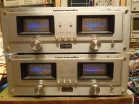
Yes, but that one is hideous! Notice how the red scale in the meter isn't illuminated at all? It hurts to look at it, I used to sell them way back. That's a 3250B preamp on top, I have a 3650 and an SC-9 preamp.
From the looks of it, it has been very poorly serviced. I wouldn't buy it!
I made some changes that lower noise and remove the "edgy" sound. The solid brass bolts on the front are used when I modify one if the client wishes.
These are two of mine. I should take a picture that better shows how they look. The bright bench lights wash the picture out.
Attachments
My noobish view on the subject is, that today we already have light and effective devices with possibility of great regulation and headroom called smps. I built a chip amp with a very humble one and it sounded great. Especially in long bursts and high levels. To me it doesn't make much sense to use linear supply in a powerful SS amp anymore.
Hi. Fuses are good thing for safety of your amplifier, but a few things needs some attention. So , fuses on each rail, after main capacitors, in a way of plus and minus to each channel to amplifier boards, lets say so. What happens,if output transistors fail shorted, and just one fuse blows? Negative rail will appear on positive and so , damaging amplifier more. So a diodes to ground must be used to blow second fuse too. Anode to gnd fot positive rail, cathode to gnd for negative rail.
Another thing , which i dislike even more, is resistance of fuses. Recently had to make a kinda of power bank of 50pcs li-on cells ,entire bank measured less than 1mR in total. Put them in box and added a automotive fuse , mounted with screes, 40ampere , and that fuse and some massive wires added 8 milliohms to powe bank resistance! Btw , wires were 10mm2 . So value about 100milliohms for smaller fuses like 4 or 6A looks rvery ealistic, and may cause some problems too, if fuse is in-between two capacitors ( amplifier boards needs to have it's own local decoupling capacitors too! ) . So it's a bit risky to have fuses on each rail. Placing fuses in secondary winding patch is even more problematic, fuses either must be slow , or high ampere rating, because of massive current drawn , during turn on.
Another thing , which i dislike even more, is resistance of fuses. Recently had to make a kinda of power bank of 50pcs li-on cells ,entire bank measured less than 1mR in total. Put them in box and added a automotive fuse , mounted with screes, 40ampere , and that fuse and some massive wires added 8 milliohms to powe bank resistance! Btw , wires were 10mm2 . So value about 100milliohms for smaller fuses like 4 or 6A looks rvery ealistic, and may cause some problems too, if fuse is in-between two capacitors ( amplifier boards needs to have it's own local decoupling capacitors too! ) . So it's a bit risky to have fuses on each rail. Placing fuses in secondary winding patch is even more problematic, fuses either must be slow , or high ampere rating, because of massive current drawn , during turn on.
I see I posted silly answer, thinking the thread took different direction. My first idea was also why not use 0.01R shunt resistor? Maybe even fusible resistor for extra safety. At 5A it's 50mV which I think is pretty detectable, but still marginal drop. The circuit shouldn't be difficult too. If you dont't like relay, you can use mosfet as swithing device. Also the problem with only one rail falling can be solved easily.
Just to illustrate 2 scenarios with 4,700uF and 10,000uF with 4ohm load (speaker impedance matters) and transformer with 0.3ohm coil resistance (I just simulate the positve rail).
You get around 1V more usable from the power supply with 10,000uF. Going beyond 10,000uF will not make much difference regarding ripple.
This is for continuous operation. I'll simulate the burst.
View attachment 1414127
View attachment 1414128
View attachment 1414130
A superb demo Ron. I was wondering if you could on, the SPICE simulator, introduce an 0R5 Ohm resistor on each side from the main smoothing capacitor to the amplifier? These would represent the resistance of the power feed wires to the board (maybe inadequate gauge?) and the resistance of a fuse and its connectors please? I would be interested to see how large the instantaneous voltage drop will be and also if Intermodulation Distortion increases... using say a large 100hz signal and a much higher frequency simultaneously....I guess I'm trying to justify the engineering I put into making an amplifier as "solid" as I can. It would be nice to know if huge copper bus bars that are used in some amps are just a ridiculous overkill
The bars are daft when you realise that skin depth in copper at 10 kHz is just 0.6mm, and the Class AB switching goes a lot higher than that.
Also ... 0R5 is extremely high for a fuse resistance in the current ranges you might possibly be worried about.
Honestly, voltage drop at high current is a fact of life. You also have the impedance of the power transformer and the AC mains before that. Plus anything else that might cause a dip in your mains even outside your house. Decent amplifier designs reject all this.
Again, a few volts dip on currents peaks is expected. You are concerned with a couple volts here. Really? I say again, if a couple volts makes any difference to you, build a much higher powered amplifier. Once you see real world voltage dips at high power using an oscilloscope, you'll understand.
One other comment. As far as power supply noise is concerned, high frequency is much more difficult to regulate or filter out. So it stands to reason you want to avoid making it to begin with. 120 Hz ripple is much easier to cure and reject than 1 KHz or higher (SMPS). I've worked on large power amps using SMPS supplies (Carver PM 2.0t for example). The switching noise can get into grounds, mains - everywhere. The higher the frequencies you generate, the further and easier it may radiate. I don't have any problems with an SMPS as long as you shield the heck out of it and ensure the shielding is effective. You also must keep HF energy out of the grounds, and your DC output lines will have filters which may well have higher impedance than a normal linear supply. Also, your feedback loop BODE response for the error amp in your SMPS probably doesn't go high enough to deal with audio peak frequencies. That means you are back to an output capacitor close to the load.
When you design anything, look at the big picture and realistic conditions. Leave the simulator behind folks and use your head, then put some stuff up on the bench and look at the real world.
Hello!A superb demo Ron. I was wondering if you could on, the SPICE simulator, introduce an 0R5 Ohm resistor on each side from the main smoothing capacitor to the amplifier? These would represent the resistance of the power feed wires to the board (maybe inadequate gauge?) and the resistance of a fuse and its connectors please? I would be interested to see how large the instantaneous voltage drop will be and also if Intermodulation Distortion increases... using say a large 100hz signal and a much higher frequency simultaneously....I guess I'm trying to justify the engineering I put into making an amplifier as "solid" as I can. It would be nice to know if huge copper bus bars that are used in some amps are just a ridiculous overkill
If we introduce 0.5ohm after the capacitors as a way of emulating fuses, cables and connections, you loose considerable power.
A good construction and selection of fuses would not reach 0.5ohm. You have to build with much less total resistance.
Even though you loose power, as long as the output doesn't get close to the rail voltage, there will be no distortion caused by this resistance.
You can decide to increase voltage and be more relaxed with resistances (less efficiency) or you make the resistances smaller (more efficiency).
But, as an exercise, let's see the results with this scenario with 2 sine waves 100Hz +1kHz superposed.
In this example, using 4,700uF plus 0.5ohm, you drop from 83W maximum to around 59W without distortion.
Max power 59W - no distortion.
If pushing power a little bit to 64W, you get wave clipped.
Attachments
About real world, here's an amplifier I built in the middle of 90's and still works fine, although I don't use it - too much power for me now that I'm older.
It delivers around 400W per channel @ 4ohms and can be operated continuously with sine wave for hours - this was the intention at that time.
There are no huge cooper bars, I just used regular cables and fuses just to support what needs to be supported ("good enough").
4 pairs Hitachi 2SK1056 / 2SJ162 per channel.
Last edited:
I think that it is worth noting that fuses will have an "(i^2)t" rating in the spec sheet that lets you get the time to blow as a function of the rms current squared. This is normally given at some ambient temperature, also in the spec sheet.
- Home
- Amplifiers
- Solid State
- fuses on amp power rails