You asked for my opinion, I have to agree with Brian here.
So with the criteria you list some form of horn type enclosure is what you should do.
Edit:
And the 3015LF does like some box volume, not sure if the more compact designs are optimal for that driver.
it reach 200....uh? Why that cult of making a sub a kick bin. I mean i don't effin.care above 100 or even 90, but looks like there was or is a fashion of having a cabinet that can cover as wide as possible.gezz
With wall that thin and with a high-ish xmax driver you need to make the box more solid, you also said that top-end is worthless.The higher the subwoofer can go, the easier it is to blend it with the main speakers.
... With a TH, the internal panels help to stiffen the box.
So with the criteria you list some form of horn type enclosure is what you should do.
Edit:
And the 3015LF does like some box volume, not sure if the more compact designs are optimal for that driver.
Last edited:
Hello Maxolini,
Taking other projects as inspiration and lessons learned is very important, but just copy and paste and build a plan as it is, I don't think is the best approach, unless you like the results and are going to use the same driver.
So you already defined the driver: kapalite 3015LF 8 The next step is to defined box design to use.
You can achieve a good result with many different design options, but in order to avoid them to be overwhelming I will mainlly stick with Tapped Horn because looks like you prefer this type, here are my suggestions.
Once you defined that you don't need frequencies above 100Hz, it make a lot of easier and basically almost everything will work. This is your Upper limit.
kapalite 3015LF 8ohm version has the Frequency Resonance of 44Hz, so this is your lower limit.
If you do not have much experience building loudspeaker I'd suggest starting from the models that are more friendly to build with less panels and preferable orthogonal (90deg) panels.
Each tapped Horn Project has a different design freedom that you can use to optimize the frequency response. They also have different aspect ratios.
Candidates to eliminate and reasons:
TH-MWTH - This design has a long path in order to reproduce very low frequencies, considering 44Hz, this is not the way.
TH-OTHORN - This design has a long path in order to reproduce very low frequencies, considering 44Hz, this is not the way.
Candidates to evaluate and reasons:
TH-SF - The easiest TH to build but the concern here is the box ratio, it can be very tall.
TH-DF - The second easiest TH to build, once it adds a second fold, the box aspect ratio is improved and so you have more freedom to adjust.
TH-BS - This is a very nice design proposed from Brian Steele (POC#7), it's also medium difficult to build, the output is a like paraflex family with a kind of "resonator" shape, currently it has no flare in the output witch improves build process, flare can be added. Note: Flare in the output help to improve Upper frequencies limit.
TH-CYCLOPS-a - This design has dual horn path, many guys from the community "high order quarter wave society" witch are move focused in the paraflex model, they say that dual path improve the load in the driver's cone making it survive for longer time due to symmetry, the majority of the design are asymmetric so people are warning you about the driver you choose has a very light cone, so it means it has low mechanical resistance, reducing compression ratio is the way to go, dual path is also preferable but not mandatory as the compression ratio. I think this model can became very heavy due to the amount of internal panels but in the other hand you would need less braces also.
TH-MTH1 - This design is also a very nice option once it has a lot of orthogonal panels
TH-MTH2 - Compared to the version 1 with this design you can adjust little more the output to improve upper limit and the driver stands in a vertical position. Brian Advocate that this position is better and safer for the driver when they are in the storage. If you like, check all models that the driver sits in vertical position, or just storage the box in the way that the driver remains in vertical position if possible.
TH-Cubo - This is the one you choose from Jbell, you can adjust it for your driver.
TH-T18 - Considering your frequency range 44-100, I'd prefer to check T18 over Cubo once it's easier to build.
TH-SS1 - This one is classic and Jbell has a design for this model using a single sheet of plywood, There are many variations.
TH-SS2 - This model is an improved design compared to the version 1 because if has a cone correction integrated in the model, so you gain benefit of box internal volume. This model one of the hardest to build.
TH-THAM - I see no particular advantage for this model compared to the others, the only benefit here is if you want to build the plan as it's shared from martinsson or if you prefer this aspect ratio.
I would take into consideration the Paraflex Type C and the Manifold-MTB, because they can provide better frequency response and they are easier to build compared to a TH.
If your intention is to use Screamers furysub, Apache H15 And jbell 2' cube as they were defined from their designers as they are without modification, other guys already helped you.
https://freeloudspeakerplan.rf.gd

Yeah , advice taken, i know that 3/4" ply is the standard for cabinets, Jbell builded the cubes and liked them a lot with 1/2" ply.You asked for my opinion, I have to agree with Brian here.
With wall that thin and with a high-ish xmax driver you need to make the box more solid, you also said that top-end is worthless.
So with the criteria you list some form of horn type enclosure is what you should do.
Edit:
And the 3015LF does like some box volume, not sure if the more compact designs are optimal for that driver.
So I want to repeat the recipe.
Btw anyone know if screamerusa still hang around? His website is not up, i was hoping to get the plans of his furysub. That he build for a club and he commented thoroughly on the collaborative tapped horn thread.
The tops he made for them was some otop variation.
Kind of what Jbell done for the stadium horn.
Best.
Max.
Wow!!Hello Maxolini,
Taking other projects as inspiration and lessons learned is very important, but just copy and paste and build a plan as it is, I don't think is the best approach, unless you like the results and are going to use the same driver.
So you already defined the driver: kapalite 3015LF 8 The next step is to defined box design to use.
You can achieve a good result with many different design options, but in order to avoid them to be overwhelming I will mainlly stick with Tapped Horn because looks like you prefer this type, here are my suggestions.
Once you defined that you don't need frequencies above 100Hz, it make a lot of easier and basically almost everything will work. This is your Upper limit.
kapalite 3015LF 8ohm version has the Frequency Resonance of 44Hz, so this is your lower limit.
If you do not have much experience building loudspeaker I'd suggest starting from the models that are more friendly to build with less panels and preferable orthogonal (90deg) panels.
Each tapped Horn Project has a different design freedom that you can use to optimize the frequency response. They also have different aspect ratios.
Candidates to eliminate and reasons:
TH-MWTH - This design has a long path in order to reproduce very low frequencies, considering 44Hz, this is not the way.
TH-OTHORN - This design has a long path in order to reproduce very low frequencies, considering 44Hz, this is not the way.
Candidates to evaluate and reasons:
TH-SF - The easiest TH to build but the concern here is the box ratio, it can be very tall.
TH-DF - The second easiest TH to build, once it adds a second fold, the box aspect ratio is improved and so you have more freedom to adjust.
TH-BS - This is a very nice design proposed from Brian Steele (POC#7), it's also medium difficult to build, the output is a like paraflex family with a kind of "resonator" shape, currently it has no flare in the output witch improves build process, flare can be added. Note: Flare in the output help to improve Upper frequencies limit.
TH-CYCLOPS-a - This design has dual horn path, many guys from the community "high order quarter wave society" witch are move focused in the paraflex model, they say that dual path improve the load in the driver's cone making it survive for longer time due to symmetry, the majority of the design are asymmetric so people are warning you about the driver you choose has a very light cone, so it means it has low mechanical resistance, reducing compression ratio is the way to go, dual path is also preferable but not mandatory as the compression ratio. I think this model can became very heavy due to the amount of internal panels but in the other hand you would need less braces also.
TH-MTH1 - This design is also a very nice option once it has a lot of orthogonal panels
TH-MTH2 - Compared to the version 1 with this design you can adjust little more the output to improve upper limit and the driver stands in a vertical position. Brian Advocate that this position is better and safer for the driver when they are in the storage. If you like, check all models that the driver sits in vertical position, or just storage the box in the way that the driver remains in vertical position if possible.
TH-Cubo - This is the one you choose from Jbell, you can adjust it for your driver.
TH-T18 - Considering your frequency range 44-100, I'd prefer to check T18 over Cubo once it's easier to build.
TH-SS1 - This one is classic and Jbell has a design for this model using a single sheet of plywood, There are many variations.
TH-SS2 - This model is an improved design compared to the version 1 because if has a cone correction integrated in the model, so you gain benefit of box internal volume. This model one of the hardest to build.
TH-THAM - I see no particular advantage for this model compared to the others, the only benefit here is if you want to build the plan as it's shared from martinsson or if you prefer this aspect ratio.
I would take into consideration the Paraflex Type C and the Manifold-MTB, because they can provide better frequency response and they are easier to build compared to a TH.
If your intention is to use Screamers furysub, Apache H15 And jbell 2' cube as they were defined from their designers as they are without modification, other guys already helped you.
https://freeloudspeakerplan.rf.gd
that was a very! Informative list Mr. Sansui.
Highly appreciated.
I plan to use 1/2" ply as the 2' cube
So I will need some carefully bracing but just the minimum for weight constraints.
As I read the whole thread were the cube originated Jim do not used any bracing but adviced us to add some if we will run hard the cabinets to save a couple db from being lost due to flexing.
Also I would like to build one of the stadium horns but that will be later on. And for fixed install.
I plan to start publishing the freq response of the cabinet when built.
Cheers.
Max
If your intention is to use Screamers furysub, Apache H15 And jbell 2' cube as they were defined from their designers as they are without modification, other guys already helped you.
https://freeloudspeakerplan.rf.gd
The Apache 15, from the image, looks like a single-expansion TH, and I have some concerns about the first section of the fold and how well that can translate to a Hornresp sim. The SS type fold allows for dual-expansion and provides built-in bracing for the top panel as well, in a cabinet with similar dimensions. If I had to choose between the two folds, I'd go with the SS fold.
JBL's use of 1/2" ply for the 2' cube likely means that box losses (due to panel flex) are going to be higher than expected compared to if the cabinet was more rigid. This would tend to smooth out all the peaks in the response curve, including the peak around 50 Hz predicted by the Hornresp sim.
I think the JBell 2' cube is more like the TH-MTH1 rather than the TH-CUBO, BTW. The TH-CUBO doesn't have the "g" panel in the diagram. Like the Apache 15, it is also a single-expansion TH.
BTW, Based on my experience with POC#2, boxes in that type of square form factor can end up being a pain in the butt to move around. Boxes with a rectangular form factor are easier - just put corner wheels at the bottom and a handle on top, and then you can just tip them and wheel them into place. Also, with a 2' width, you probably can't fit two side-by-side in a car unless the trunk is at least 48" wide ...
Last edited:
Thinking in terms of structural needs, the driver you choose offer only 450W and so you don't need the same reinforcements as 1500W one but, consider that you are a not working for an engineering company it means you probably are not going to use software FEM software to optimize the box in terms of structure so as DIY you need to choose the safe path. Using a 1/2" ply is a risky you need to evaluate because you are spending a lot of money and time.
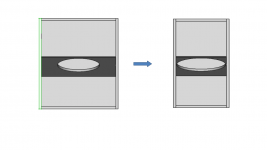
Considering that, I would reduce the box width as much as possible, the minimum needed to assembly the driver, this will help to make panels stiffer. See attached image. Doing that you will change the aspect ratio of the design. If you fix the width, the design options will start to show more differences making it easier to choose the best one for you.
You need to find something to support you to pick the right design, it can't be random, puts more ration behind it. For instance Brian is point about where you will transport the box, think about more constrains to consider. Each design offer a different grade of freedom, like, compression ratio, how many expansions, , how many folding, how many panels, driver position, and so one. They will result in different performances. So if you define more constrain, slowlly we can eliminate some options and find the best candidate. Once you pick one, lets modify it to you needs.
Attachments
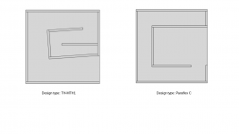
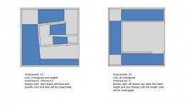
Take a look at the practical comparison attached as an example and check the differences.
Tapped Horn MTH1 vs Praflex C
Did you already compared the performance you can achieve with both designs? SPL, Diaphragm displacement, Group delay, etc
Tapped Horn MTH1 vs Praflex C
Did you already compared the performance you can achieve with both designs? SPL, Diaphragm displacement, Group delay, etc
Attachments
Brian and Sansui,
let me take a look at your posts later today.
too much info for a mere sub DIY mortal 😀
Many thanks for donating your time and experience in to my quest.
Best,
Max.
let me take a look at your posts later today.
too much info for a mere sub DIY mortal 😀
Many thanks for donating your time and experience in to my quest.
Best,
Max.
IMO, the ODTL, the TH and the Paraflex alignments are all basically attempts to deal with the impact of harmonic resonances on the combined output of the system.
With the ODTL, the first (and most troublesome) resonance is nulled out by locating the driver partway down the path. There is however a small price to pay in terms of efficiency with this design (compared to an end-loaded TL).
With a TH and the Paraflex (when both are designed properly), the intent is to "fill in" the dip in the response caused by this resonance, without giving up anything in terms of efficiency. However the phase behaviour in this "summing area" in the frequency response is not very smooth, which does make the idea bit suspect.
In terms of peak output, the TH and Paraflex will likely beat an ODTL (using the same driver). Large "vent" = less compression at peak volumes. But the boxes are larger, sometimes much larger.
These days, my preference is for ODTL alignments. The box is smaller and easier to move, and amplification is cheap, and no special filtering is needed to get the best results from them. YMMV 🙂
Hey Brian,IMO, the ODTL, the TH and the Paraflex alignments are all basically attempts to deal with the impact of harmonic resonances on the combined output of the system.
With the ODTL, the first (and most troublesome) resonance is nulled out by locating the driver partway down the path. There is however a small price to pay in terms of efficiency with this design (compared to an end-loaded TL).
With a TH and the Paraflex (when both are designed properly), the intent is to "fill in" the dip in the response caused by this resonance, without giving up anything in terms of efficiency. However the phase behaviour in this "summing area" in the frequency response is not very smooth, which does make the idea bit suspect.
In terms of peak output, the TH and Paraflex will likely beat an ODTL (using the same driver). Large "vent" = less compression at peak volumes. But the boxes are larger, sometimes much larger.
These days, my preference is for ODTL alignments. The box is smaller and easier to move, and amplification is cheap, and no special filtering is needed to get the best results from them. YMMV 🙂
i am having a hard time pulling the Furysub from the thread, looks like there was an updated one on screamerusa site but it is down now
i tought there was a repository place where the old sites was mirrored i dont know if it can work on screamers
on the thread him says that because the design have a narrower mouth there was compression and that protected the driver from damage,
so can you DAMP the driver from too much stress with air compression i mean acoustics?
what caught my eye on the furybox is that the ditortion was bare minimum according to him, there was people from big sound companies
to go an hear his system cause word of mouth got spread on how good it sounded
also he stated that because the low distortion i can get much louder and people dont notice it, i mean
people are used to distorted sound systems and they perceive that as LOUD
so when you remove the the distortion people precieve it as less LOUD cause they are not used to experience low distorted system
once i heard a MEYER system , i dont rember the model numbers because at the time i wasnt in to music nor cabinet design and DIY
it was back in the mid 80's
it was on a big hall where a famous cover band from the time was playing on a wedding
it was Punchy LOUD.... but you it didnt hurt your ears or make your ears bleed like the rest i have heard
and you can have a conversation almost in front
now i learned that was a low ditortion system
one thing that notice is that there was racks of CREST CA amps
so i guess Crest CA was clean and good at the time.
FOUND IT !!!
at least on this forum
the furysub is in screamerusa's thread: http://www.diyaudio.com/forums/subwoofers/131852-live-sound-specific-tapped-horn-thread.html, there is a lot of interesting stuff in that thread, here are a few items:
- Page 52/53/54/55 have all kinds of interesting comments on the actual construction by screamerusa,
- initial attempt at drawing, Post #530,
- interesting comment by jbell, Post #532,
- updated drawing, Post #535,
- screamerusa's comments on box and drawing, Post #537,
- GM posted interesting observations by Tom Danley, Post #544,
- attempt at AkAbak, Post #563,
- Posts #579/580 Hornresp SPL plots,
- Hornresp Input screens, and references, Post #583,
- altered version by runrod1948 in Posts #715/717,
Last edited:
ok, the cube is discarded
Jbell comment for the SS15
post#59
https://www.diyaudio.com/community/threads/single-sheet-th-challenge.170771/page-3
so its down to the Furysub and SS15
EDIT.
and maybe paraflex C, its worth to do the SPL graph to see if we can do something good with the 3015LF
sooo easy to cut the wood on the Paraflex C layout and bracing
2 Boxes or more minimum to bring up the 40hz, and it's a party.
Anyone considering building cubes forget it.. this trounces the cube. Anyone considering building the big box, unless you REALLY need sub 40hz, forget it -- build this.
Here's the numbers:
40hz 98.5
45hz 100.5
50hz 102
55hz 103.5
60hz 105
65hz 105
70hz 105
75hz 104.5
80hz 104.2
85hz 104
90hz 104
95hz 104
100hz 104.5
105hz 105
110hz 105
115hz 105.5
120hz 106.5
Last edited:
These days, my preference is for ODTL alignments. The box is smaller and easier to move, and amplification is cheap, and no special filtering is needed to get the best results from them. YMMV 🙂
I think a negative flare TH will match or beat an ODTL in size and output.
Bandpass 4 life!
I read that any F..up in the design or build and you Fry your driverI think a negative flare TH will match or beat an ODTL in size and output.
Bandpass 4 life!
the Bandpass are very UNFORGIVING on the contruction.
What Design you suggest for the 3015LF
found a furysub planIMO, the ODTL, the TH and the Paraflex alignments are all basically attempts to deal with the impact of harmonic resonances on the combined output of the system.
With the ODTL, the first (and most troublesome) resonance is nulled out by locating the driver partway down the path. There is however a small price to pay in terms of efficiency with this design (compared to an end-loaded TL).
With a TH and the Paraflex (when both are designed properly), the intent is to "fill in" the dip in the response caused by this resonance, without giving up anything in terms of efficiency. However the phase behaviour in this "summing area" in the frequency response is not very smooth, which does make the idea bit suspect.
In terms of peak output, the TH and Paraflex will likely beat an ODTL (using the same driver). Large "vent" = less compression at peak volumes. But the boxes are larger, sometimes much larger.
These days, my preference is for ODTL alignments. The box is smaller and easier to move, and amplification is cheap, and no special filtering is needed to get the best results from them. YMMV 🙂
Screamerusa comments
"
One side of each piece is cut at about a 12 degree angle, yes.
15x29cm is the original opening, correct.
I will do some rechecking in a couple of days as this is my bust part of the week. The drawing looks spot on.
Removing the other reflectors all yielded unacceptable dips and losses.
The one "missing" reflector was my insane atempt to "cut" the path length and create a higher spl "Bounce" affecting the 100hz area as I was not getting ANY gain over the direct radiator.
Please remember that the goal was not to build the best tapped horn live sub (That's Tom's job), but to match or exceed a double driver cabinet to eliminate the amount of amps and wall power required to achieve high quality high spl with a 2.6ohm minimum load (3 drivers).. Smooth response at about 102-103 db from 38-125hz would be a realistic goal, for a single"
A TH and ODTL are the same physical enclosure.
Both enclosures can be single, double, etc. folds.
TH = internal driver mounting.
ODTL = external driver mounting.
TH = BP6S.
ODTL = BR.
Both enclosures can be single, double, etc. folds.
TH = internal driver mounting.
ODTL = external driver mounting.
TH = BP6S.
ODTL = BR.
On the FurySub thread GM shared some theory comments from Tom Danley. that i do not fully get but you guys that know a lot more sub theory design can digest easily.A TH and ODTL are the same physical enclosure.
Both enclosures can be single, double, etc. folds.
TH = internal driver mounting.
ODTL = external driver mounting.
TH = BP6S.
ODTL = BR.
"Hi John, all
I would certainly second Marshal's horn paper, I have made dozens and dozens
of horns based on his math (for the driver / horn
relationship) over the last 12 years or so and his alignments
(relationships) work well, even into the HF range.
Bottom line I suppose is that the "important" part is that when you build a
real horn that it measures like the computer prediction
and since most horns I have built were not "full ideal size", having
Marshal's math as a starting point, followed by modeling of the
real thing has proven to be most powerful.
For example, when the horn mouth is smaller than ideal, it may turn out that
some other profile (other than the t = X as defined
by the computer) may provide better results. Similarly, as in the LAB
project, for cases when fewer than "ideal" numbers are
used, a somewhat different driver gave better results. With that project I
started with the "ideal" driver and then on the real horn
model used that driver as a starting point, looking at a set of 2, 4 and 6
boxes and diddling the parameters to get the best
results.
As for curves vs reflectors, it would depend entirely on the acoustic
dimensions.
As a rule of thumb, when an obstacle is under about 1/4 wl in size, sound
goes around it, no problem, the object is acoustically
invisible..
If an object is say 10 wl across, it begins to make a pretty good reflector.
In a folded horn, the bends have a direct bearing on the results higher up.
When the difference in the acoustic path length between the inside and
outside radius of the bend reaches 1/2 wl, there will be a
deep cancellation notch in the response.
This is why most all the folded bass horns I design have minimum angle bends
and those bends tend to be wide rather than deep
(to push the cancellation F's as high as possible).
For a real woofer horn though, this corner issue is a non issue.
Once we had a customer who distributed our servodrive horns in Italy.
He wanted to make his own boxes to save shipping and we said ok send us one
to look at / measure first.
He was very meticulous, had all the corners glassed in, all of the inside
was smooth and aerodynamic like an airplane part.
It really did look cool and obviously he spent a lot of time making it
perfect.
Our cabinet shop had made up a sample horn with no curves (using flat
reflectors) and another with nothing at all in any corners
except the final bend.
I measured each box with the same driver module, in the same location, with
the same mic and TEF machine.
I measured at rated power and 1/10 to see if there were differences.
The TEF machine is repeatable to a tiny fraction of a dB so the most
informative way to look at the plots was to overlay them.
The highest SPL's were from the prototype without corners, second was the
normal production model and last (about 1.5 dB
down) was the aerodynamic one.
Distortion was essentially identical for all units.
The results were sort of a surprise however on examination, it was clear
that even thought the BT-7 could produce a large
acoustic power (about 200 acoustic Watts each, in a group of 4), the air
motion in the throat and passageways was not a
sufficiently high speed to benefit from the aerodynamic treatment.
Also, that filling in the corners reduces the actual volume of air in the
horn making it "smaller" than the unfilled unit.
Granted, this box is never used above 120 HZ and usually under 80 Hz so hf
performance is not normally a concern.
One can improve some aspects of real hf performance in a folded horn of
large dimensions by using a reflector style corner.
Reflectors are common in microwave frequencies in antennas because wave
theory also applies.
With sound in a folded horn, one finds that no matter how it is done, there
is a region between where there is the 1/2 wl path
length cancellation and where the reflector really works (and remember the
acoustic path for a reflector and mass flow are also
different) that is undesirable (chaotic) so where you see reflectors used in
antenna's, they are limited to the range where they
ARE reflectors, just like with sound, the in between range is undesirable.
If one was designing a folded horn for use higher up in frequency, a second
thing to be aware of is the mode translation which
means that when the parallel walls are acoustically 1, 3, 5 etc. 1/2
wavelengths and large enough in area, there is a deep notch in
the response. This is because there is a standing wave between the two walls
which the desired acoustic output drives.
Driving the resonance also taps out the desired acoustic signal's power and
so at the mouth is a notch.
This is the source of the notch on the lab sub who's internal width is 21
inches, 1/2 wl @ 21 inches ~ 1/2 wl @ 323 Hz.
As also mentioned, the front volume (trapped between the radiator and
throat) can be sized to extend the hf response.
This uses the air volume compliance acting against the air mass in the
throat to make a low pass filter like the vent is on a vented
box.
The difference here is that the resonance defines the upper cutoff on the
horn and lower on a vented box.
This "filter" if it can be sized correctly, has an additional advantage.
The Unity, LAB sub and BT-7 all have the front volumes sized to produce the
hf extension BUT after the high cutoff the roll off
is 1 order steeper than before.
This means that the harmonic distortion that is inevitable with any driver
is attenuated before being radiated (as those harmonics
are above the cutoff).
In the Unity, the driver placement on the horn walls also adds an additional
low pass filter which further attenuates out of band
signals from being radiated. The horn loading combined with this effect are
in the Unity's which typically measure about 1/10 or
less the midband THD of anything I have measured.
On the oother hand, often it is not practical to use this trick, like hf
compression drivers where this air volume is smaller than can
be achieved as it is.
Some one also asked about compression ratio and what effect than has, I
would suggest they dig through the design part of the
LAB sub as I had written about that (from my perspective) there.
In short, compression ratio is a "transformer" and one is adjusting the
turns ratio.
Why that effects BW and efficiency is in the LAB stuff and too much to write
now.
Well, I have speakers to work on, got to run
Tom Danley
Servodrive / Sound Physics Labs"
It might match it, but the horrible out of band filtering would put it out of the running for me. If I was going to go bandpass with a smaller vent than what the TH provides, I'd just go with a simple shelf-vented offset driver bandpass design, which would provide similar response with lower out of band noise issues. My "Enigma" build for example can essentially be run without a HP filter.I think a negative flare TH will match or beat an ODTL in size and output.
Bandpass 4 life!
Hmm... maybe that 3015LF might do well in an offset-driver 4th order BP or "augmented" 4th order BP (basically a BP6S with a low-tuned lower Fb that improves power handling at low frequencies without significantly changing the frequency response. )
Brian is right. ODTL trumps a TH when you choose small and low.
Light = ODTL.
Dark = straight flare TH.
Both enclosures are the same dimensions L x W x H.


Light = ODTL.
Dark = straight flare TH.
Both enclosures are the same dimensions L x W x H.
Last edited:
some theory comments
Read and learning is very nice and addictive, but it may confuses too, because there is always the context when the text was posted, people may not have enough time to invest in your project as you have. In addition things was improving during the years and so one.
I would suggest to start from a practical point of view, lets directly compare things, so you decide the best option for you and lets move on.
There are so many designs, so many options, so many comments, it may paralyze you to move forward. Remember that personal taste is also involved here.
Regarding Paraflex, there is a group in Facebook, see link below. Many people are from USA, you can try to contact them, maybe listen to a box personally before take a decision to build. many guys said that they would never back to a Tapped Horn once they build Paraflex and they consider an improved design. I can't judge it, but many simulations I've seen are better so it make sense.
https://www.facebook.com/groups/bassaz/
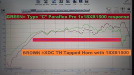
They have a thread here too, I remember they post a Paraflex comparison using real measurements vs TH18 designed from Xoc1 (TH-SS style), try to find it and see if it helps you to take a decision.
https://www.diyaudio.com/community/...lanar-horns-and-pipes-concepts-builds.309352/
Martinsson, was the designer for THAM, it is a Tapped Horn, and he also designed the ROAR series, you will see him in many posts says that ROAR are better than THAM. Check his website below.
http://www.martinsson.cc/blog/
So, maybe it's the time to start to find answer to reduce the amount of option.
If you really need from 40Hz to 100Hz, go higher order designs
If you need extension, go Direct Radiation Design.
At least between those two design family I think you already have enough data do make a decision.
Attachments
- Home
- Loudspeakers
- Subwoofers
- Furysub, Apache H15, or Jbell 2' cube