Yes, I understand. In other words, the amplifier gets excited by output load capacitances somewhere lower than 100nF, so to keep the amp totally stable a minimum load capacitance of 100nF is provided.john curl said:It is possible with some amp designs to have a critical load cap value that is rather small. Then, if you load the output with a larger value cap, but not so large that it current limits the amp, then you get unconditional stability. I have done this in a real power amp design.
This seems odd because, conventionally, the idea of the RC shunt BEFORE the series L/R achieves the same thing, but you don't end up hanging a weight across the signal path to the speaker. As Bob points out, it is normal to keep the path inductance of the RC shunt as low as possible to keep the amp damped at HF. The Bryston appears to have a pretty significant path length...the 100nF being on a separate PCB.
I don't know whether the Bryston is a low GNFB design or high.
Brian
Slew rate spec noted...not necessarily the slew rate seen at the amp output terminals, ok. Isn't this a bit like saying a car's engine is capable of 0 to 60 in 5 seconds, when the car itself can only manage 0 to 60 in 10 seconds?
I think thats the wrong analogy... in cars they DO in fact diffirentiate between horesepower at the flyweel and at the driving wheels...
IMO what Anatoly (Wavebourn) said about a series output resistor makes sense.
Even a resistor of only 0.1 Ohms would give some isolation from the load but wouldn't decrease DF very much. DFs above 50 are usually enough IMO. To me it seems more important that an amp's output resistance is
1.) Real
2.) Frequency independant
3.) indepandant of output current or voltage (i.e. linear)
rather than having a very low output resistance.
Regards
Charles
Eva said:When the 100nF capacitor is placed after the inductor without no RC before the inductor, a combination of RLC load values exists that makes the amplifier oscillate. This external RLC will resonate with the internal 100nF and parasitic inductance resulting in a high impedance peak as seen from the amplifier side. If you adjust the external RLC values so that the system becomes tuned close to the unity-gain crossing region, BANG!
Hi Eva,
Can you gives us an example plus values of such devastating combination?
As for your post #175, I like to responds, but can't upload the accompanying schematics and graphs due to an server error. (No, they are not too large!)
Cheers,
Edmond.
john curl said:It is possible with some amp designs to have a critical load cap value that is rather small. Then, if you load the output with a larger value cap, but not so large that it current limits the amp, then you get unconditional stability. I have done this in a real power amp design.
Hi John,
I've observed the same phenomenon, but making an amp unconditional stable with a 'larger' cap, I consider that as very crude, not to say bad practice.
Cheers,
Edmond.

The kind of phenomena that could destroy an amplifier for no apparent reason... There are parasitic RLC systems everywhere, not just inside switching mode power supplies and class D amplifiers.
That's true.Nordic said:I think thats the wrong analogy... in cars they DO in fact differentiate between horsepower at the flyweel and at the driving wheels...
I'm choosing to use these mechanical analogies:
C = mass
L = spring
V = velocity
I = force
So I'm mapping voltage slew rate to acceleration (rather than top speed, John). I am familiar with cars' acceleration being specified at the wheel/road interface.
Eva said:The kind of phenomena that could destroy an amplifier for no apparent reason... There are parasitic RLC systems everywhere, not just inside switching mode power supplies and class D amplifiers.
Thanks, Eva.
But will you encounter such output load in real life with class-A/AB/B amplifiers? I don't think so.
Cheers,
Edmond.
PS: I still can't upload pictures, maybe tomorrow?
I'm not in favour of it either, in general.Edmond Stuart said:
Hi John,
I've observed the same phenomenon, but making an amp unconditional stable with a 'larger' cap, I consider that as very crude, not to say bad practice.
Cheers,
Edmond.
To use the car analogy, can you image owning a sports car that behaves like this? You have it on your driveway with its engine running. You go to put your luggage in the boot and it begins to lurch back and forth, a little more luggage and it lurges violently. You immediately phone the dealer, who tells you that you must either drive it with no luggage at all or put at least 100kg in the boot. Anything in between is no good!
Bryston are putting 100kg in the boot. I wonder why.
Brian,
Bryston (and Cherry) did NOT put 100kg in the boot (at least not in that boot), as they put the cap behind the coil, while J.C. put it directly to the output.
Bryston (and Cherry) did NOT put 100kg in the boot (at least not in that boot), as they put the cap behind the coil, while J.C. put it directly to the output.
Eva said:In that Bryston schematic the 100nF capacitor is not placed in the best location, the amplifier is easier to disturb that way. External load capacitances and inductances can easily resonate with the internal 100nF capacitor. Placing a separate RC network before the RL provides superior immunity against any load that becomes capacitive or resonant at RF.
..........................
Hi Eva,
Whether it's not the best location depends on the envisioned purpose. Remember that Zobel networks serves two purposes: not only correcting the misbehavior of the speaker impedance at HF, but also blocking RFI from outside.
I agree with you that an external inductance (not a capacitance, btw) forms a (damped) resonator with that parallel cap. The point is does it matter? Also, how well performs the alternative circuit?
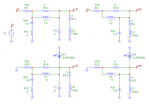
In the following examples of the two alternative topologies, I've put a 100uH inductor in series with load, representing the voice coil inductance of an average tweeter.
Below the schematics and next post the response.
Attachments
And here are the various responses. The first graphs show the output voltage as function of the input voltage. Observe that the circuit with the cap across the speaker terminals (green curve) peaks a bit, 3dB at 600kHz.
The second graphs show the impedances at the input side. Indeed, the thing peaks at 64kHz and the impedance rises to 205 Ohm. But the other circuit does exactly the same!
The last graphs show the relative susceptibility to RFI ingress. Notice that the circuit with RC at the input (red curve) does almost nothing above 1MHz, while the other circuit performs as intended.
Cheers,
Edmond.
Attachments

🙄Ok, forget the transmission as the inductor.
How about the car is attached to a trailer, via a spring and damper, and you have to put 100kg into the trailer to keep the car from wobbling? Happy?
How about the car is attached to a trailer, via a spring and damper, and you have to put 100kg into the trailer to keep the car from wobbling? Happy?
Hi Edmond,
could you add outputs 5 & 6, the interference signal delivered via the feedback path to the inverting input?
How about combining both types to form a Pi filter?
could you add outputs 5 & 6, the interference signal delivered via the feedback path to the inverting input?
How about combining both types to form a Pi filter?
quote
Many people here have little or no idea what causes power amp instability, or what is really necessary to fix it.
unquote.
Was that really necessary John?
Many people here have little or no idea what causes power amp instability, or what is really necessary to fix it.
unquote.
Was that really necessary John?
Bonsai said:quote
Many people here have little or no idea what causes power amp instability, or what is really necessary to fix it.
unquote.
Was that really necessary John?
Of course we haven't the faintest idea, that's why we, dumb as we are, are using coils.
So it was necessary. And how to fix it? Just place a large cap directly across the output! 😀
Cheers,
Edmond.
AndrewT said:Hi Edmond,
could you add outputs 5 & 6, the interference signal delivered via the feedback path to the inverting input?
Hi Andrew,
Of course I can do that, but with which amplifier?
(not now, perhaps tomorrow)
How about combining both types to form a Pi filter?
I've tried that, but with limited success. When I also put 4 Ohm and 62nF in series across the input (just as in the other circuit), the impedance peak drops from 205 to 94 Ohms at 45kHz instead of 64kHz.
Cheers,
Edmond.
just use a pair of gain=28 resistors. 27k and 1k0, just to see which circuit injects more/less interference back to the inverting input and how much.Edmond Stuart said:......I can do that, but with which amplifier?
(not now, perhaps later)
- Home
- Amplifiers
- Solid State
- Function of Output Inductor