Bonsai said:Sorry Edmond - I cannot answer your question. I looked on the web, but found no impedance curves or anything.
Hi Bonsai,
Perhaps you can measure it by yourself, next week of course.
Cheers,
Edmond.
Bonsai said:Sorry, guys, I will be away on business for the next week - maybe next week end I can try some more experiments.
BTW (you'll love this) I shorted out my output coil with a 100mm crocodile clip, and the waverform at the speaker cable showed no observable difference on the scope. I can only assume the spkr and cable inductance swamped the output coil inductance.
Next experiment I want to try is a 1uF right across the spkr terminals. My bet is without inductor the amp oscillates and with the inductor it does not.
What would be also quite revealing is the waveform at the amp output, before the coil, with/without the 1uF at the terminals and at the speaker end.
I have documented one of these scope pics in my 1984 power amp article for Audio Amateur.
Jan Didden
Bonsai said:...I used 5nH per cm, but I have also seen 10nH per cm used. Here is a pic of the cable (very, very thick cables).
With 10nH per cm, you get 6uH for the cable. do you think its higher?
Hi Bonsai,
Here is an article on calculating the inductance of zip cord. There's also a bunch of speaker cable measurements here. These measurements are on a "per foot" basis.
Andy,
Could I clarify those Audioholics measurements? It looks to me like they are L' and C' and R per unit length measurements, the L' and C' are the distributed values that can be used to calculate the characteristic impedance of the transmission lines Zo = SQRT(L'/C').
This is different from the calculation of loop inductance of a twin conductor cable. The formulas are quite different and the loop inductance is not available in L/m because the inductance is not linearly related to cable length.
Wikipedia has a formula for the loop inductance of a lossless twin wire cable at low frequencies (see inductance ):
L = length x mu x [ ln(d/a) + 0.25 ] ... if d >> 2a
L is loop inductance in Henrys
length is cable length in m
a is conductor radius in m
d is conductor separation, centre to centre, in m
mu is the permeability of free space = 4 x pi x 10^-7
Eg: a 3 m length of lossless speaker cable, with 3mm radius conductors, 1cm apart has a loop inductance of 1.7uH.
No doubt there is a formula that relates L' to loop inductance and "length" but I haven't found it yet.
traderbam said:Andy,
Could I clarify those Audioholics measurements? It looks to me like they are L' and C' and R per unit length measurements, the L' and C' are the distributed values that can be used to calculate the characteristic impedance of the transmission lines Zo = SQRT(L'/C').
This is different from the calculation of loop inductance of a twin conductor cable. The formulas are quite different and the loop inductance is not available in L/m because the inductance is not linearly related to cable length.
Wikipedia has a formula for the loop inductance of a lossless twin wire cable at low frequencies (see inductance ):
Not sure what you mean. Those Wikipedia formulas in "Inductance of simple electrical circuits" all show inductance proportional to length for the structures that could be used for speaker cable (leaving out circular loops and such).
Andy, if you go half way down you'll see a table entitled "Inductance of simple electrical circuits". There the total inductance of different shapes of circuit are give. The size matters and the inductance is non-linearly related to the size.
For example, the inductance of a 10cm long piece of wire is not equal to twice the inductance of a 5cm long piece.
There is a difference between inductance per unit length (characteristic inductance if you will) of a speaker cable and the low frequency loop inductance of a circuit containing that cable.
Bonsai, the figure of 5nH/cm I gave you was for a particular diameter of wire and of a certain length. The general formula for the low frequency inductance of a piece of lossless straight wire is:Bonsai said:traderbam, I used 5nH per cm, but I have also seen 10nH per cm used. Here is a pic of the cable (very, very thick cables).
With 10nH per cm, you get 6uH for the cable. do you think its higher?
L = 0.0002 x b x [ ln(2b/a) - 0.75 ]
where,
L is the inductance in uH
a is the wire radius in mm
b is the wire length in mm
traderbam said:Andy, if you go half way down you'll see a table entitled "Inductance of simple electrical circuits". There the total inductance of different shapes of circuit are give. The size matters and the inductance is non-linearly related to the size.
Please re-read my post to which you are responding. I'm talking about structures that could be used as speaker cable and also referred to the same section that you did.
For example, the inductance of a 10cm long piece of wire is not equal to twice the inductance of a 5cm long piece.
The inductance of a single wire is a somewhat paradoxical concept. See this page for more info.
I'm not sure what we are discussing. I assume a zip cable's loop inductance should be calculated on the basis that the conductors are tied together at one end, thus forming an elongated rectangular loop. In this case the inductance of the loop is non-linearly related to its length.
Oh, what I'm referring to is in the Wikipedia article on inductance, in the "Inductance of simple electrical circuits" table, the "pair of parallel wires" entry (appropriate for zip cord). This shows the inductance being proportional to length. Then, to get the inductance per unit length for the telegrapher's equations, you just take the total inductance and divide by the length. This is an approximation, as the inductance is a function of frequency.
This all gets back to Bonsai's original post here, in which the structure he asks about is appropriate to the Wikipedia case of "pair of parallel wires". That is, it is a cable, rather than the oddball case of a solitary wire. The solitary wire is an oddball case because there is no unambiguous way to define its inductance (per the site I linked in my earlier post).
This all gets back to Bonsai's original post here, in which the structure he asks about is appropriate to the Wikipedia case of "pair of parallel wires". That is, it is a cable, rather than the oddball case of a solitary wire. The solitary wire is an oddball case because there is no unambiguous way to define its inductance (per the site I linked in my earlier post).
Yes Andy. My mistake. You are correct. I was confused between the "circuit" equation, which is proportional to length, and the single wire equation which is not. Also, the L' is the same as the loop formula gives, which is obvious. I really shouldn't mess with this stuff late on a Sunday evening! 
I suppose the oddball equation for a straight wire is no more odd than the formula for a coiled inductor. A separate adjustment for the effect of the area of the circuit of which the wire or coil are a component should be made.
I suppose the oddball equation for a straight wire is no more odd than the formula for a coiled inductor. A separate adjustment for the effect of the area of the circuit of which the wire or coil are a component should be made.
Thanks for the input Andy_C and traderbam. I'll have to wade throught this in the next few days. One thing I want to do next is try to model this on LTspice.
Despite all th e effort everyone makes to make a nice stable amp with clean square wave response into a resistive load, it seems that physics conspires against us when we introduce a bit of inductance/capacitance via the cable. Those waveforms at the speaker terminals after 3m of cable do not look good.
(Question: for the cable, are we going with 3uH or do you have a different view - when I did a webb search, it seems there are quite a few approaches to calculating the inductance).
Hi Bonsai,
For the cable, what I've done in the past for simulation is a transmission line approach. I took some sample data of R, L and C per unit length from that Audioholics link above, then put the data into the LTRA (lossy transmission line) model. The speaker model I used was from the Stereophile web site and is from Ken Kantor I think. LTRA is an interesting model that actually simulates the telegrapher's equations. This is easy for AC analysis, as there is a closed form expression for the Y matrix. Transient is tricky but has been solved by some good folks from UC Berkeley. References are here and here.
Edit: Found the file. The 5e10 resistor is 5 Ohms in the Stereophile model but I set it to 5e10 to model an open, so I could see any resonant effects from an inductive speaker load.
Attachments
basic RLC measurements:
http://www.passdiy.com/pdf/articles/spkrcabl.pdf
simple multisection lumped RLC models likely are adequate for amplifier stability assement
if you want to dig into cable effect modeling you should 1st look into "skin effect"
a few pointers to sites I've found:
http://www.passdiy.com/pdf/articles/spkrcabl.pdf
simple multisection lumped RLC models likely are adequate for amplifier stability assement
if you want to dig into cable effect modeling you should 1st look into "skin effect"
a few pointers to sites I've found:
jcx said:http://www.circuitsage.com/tline.html
contains link to: http://www.wheeler.com/technology/technicalpaper2/technicalpaper2.pdf
"Skin Effects models for Transmission Line Structures using Generic
SPICE Circuit Simulators"
might be able to fit to two-wire cable sim Z# from QuickField magnetic harmonic analysis...
jcx said:how the big boys do it:
http://www.techonline.com/community/ed_resource/feature_article/14767
and brain numbing math applied in the name of “simplified” modeling:
http://rleweb.mit.edu/vlsi/publications/pub162.pdf
and a book I will look out for (sounds complex enough for me):
http://www.amazon.com/exec/obidos/tg/detail/-/0130289043/002-8730724-0988007?v=glance
We'll need to know the dimensions of your cable: conductor radius and typical centre to centre separation of the two conductors.Bonsai said:(Question: for the cable, are we going with 3uH or do you have a different view...
Hi Bonsai,
Plugging you numbers into the equation in post 264 gives an inductance of 2.6uH.
Perhaps Andy would give a second estimate.
Brian
Plugging you numbers into the equation in post 264 gives an inductance of 2.6uH.
Perhaps Andy would give a second estimate.
Brian
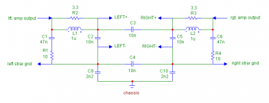
Here another Zobel network, from NAD.
Notice the 'stupid' caps (not my words!) across the speaker terminals.
Also notice C3 between the hot left and right terminal. Looks really funny. Probably done because the two channels can also be bridged, I guess.
Cheers,
Edmond.
Notice the 'stupid' caps (not my words!) across the speaker terminals.
Also notice C3 between the hot left and right terminal. Looks really funny. Probably done because the two channels can also be bridged, I guess.
Cheers,
Edmond.
Attachments
Re: Re: Re: 'mass'
There's isn't one. 🙂 I don't see how one can draw any conclusion about the sound quality of an amp from slew rate alone, provided its slew rate exceeds that of the source.Edmond Stuart said:Sorry, I don't see the connection.
edit: What are you aiming at?
- Home
- Amplifiers
- Solid State
- Function of Output Inductor