I run some more measurement sets to double check the function of SSM2141 differentials devices at output.
Yes, in one respect they are slightly worsening things: SNR is increased but by just 0.5 db, from - 81.3 to -80.8 dbV. Yesterday I had 80.8 without them...so really not relevant) . A weighted N+D went from 88.5 to 85.5 dbV A, so 3 db worst.
However, now balanced signal is completely equal, + output is same RMS as - output which was not the case without them. In addition now I can use single ended amp without issue, small noise loss is mainly in LF where it cannot be heard IMO.
As so far I changed my mind and I will keep them. Used last jumper on second stage (Rg =3k3) that gives me 1029 VRMS output (differential) from 5mV input.
Only listening can , if it can, determine whats better here.
This is then final diagram that goes inside TT now:

The preamp installed in TT , shielded by copper and connected to MM cartridge.
Here is noise floor of different situations:
Red trace is from bench measurements with test signal for reference.
Dark green , blue and orange is with preamp powered in its place and cart connected, arm placed in middle of LP. It is with no power to TT, powered TT and motor running on TT respectively. There is no obvious signal pick up from motor. Here is obvious that cart + cable in the arm pick up more HF noise than test signal cable, Probably more important is that cart is not 800 ohm resistor, its impedance goes up with frequency, hence more noise as frequency raises.....
Finally , light green trace on top is cartridge playing silent groove just to illustrate where we are in real world.
That's interesting stuff. You have mechanical peaks at (roughly) 130Hz and 340Hz. They must have a cause, and my first guess would be the motor. What frequency does it receive? Do those peaks change in frequency if you switch between 33 and 45? If not, they could be tonearm resonances. What your graph does show is that electronic noise and interference is negligible <1kHz, but gets worse as frequency increases. You have bipolar inputs, implying current noise that develops voltage noise when it passes through the MM cartridge's source impedance. JFET input avoids that problem. I also note that you have not opted for synthesised loading resistance. Given that you have a balanced topology, it would be easy to synthesise loading resistance by adding a resistor between each input and the opposite polarity's output. With JFET input and synthesised loading resistance, it should be possible to get the blue and orange traces closer to the red.
Hi , sorry might be I picked wrong silent grove with end of it where needle jumps back. I just wanted to show surface noise relative to amp noise. The mechanics of this table are well analyzed in Limestone thread, Here is picture of few silent passages, one has that bump,You have mechanical peaks at (roughly) 130Hz and 340Hz. They must have a cause, and my first guess would be the motor. What frequency does it receive? Do those peaks change in frequency if you switch between 33 and 45? If not, they could be tonearm resonances.
Given that you have a balanced topology, it would be easy to synthesise loading resistance by adding a resistor between each input and the opposite polarity's output. With JFET input and synthesised loading resistance, it should be possible to get the blue and orange traces closer to the red.
Probably I will experiment with JFET input later, have OPA2828 in mind for long. Wondering if it will be possible to hear difference.... Can you sketch or link this synthesized loading?
And one video more for fun, motor is after all visible, but only at start up as this is set up that 3 phase motor starts with higher amplitude first few seconds, than amplitude is reduced to smaller one needed to keep platter spinning.
At start up you see ramp up of motor as signal 1, then it reaches 180Hz (3 phases running at 60.61 Hz) and then when running lower amplitude is applied, its signal sinks in to noise floor.
At start up you see ramp up of motor as signal 1, then it reaches 180Hz (3 phases running at 60.61 Hz) and then when running lower amplitude is applied, its signal sinks in to noise floor.
The only reason to apply synthesized loading is to increase S/N.
But when weighted S/N is above 75dBA, improving this figure by a few dB’s serves no purpose and only complicates the circuit.
At 20kHz the surface noise is still 10dB above the preamp’s noise, so this preamp passes the test with flying colours.
Hans
But when weighted S/N is above 75dBA, improving this figure by a few dB’s serves no purpose and only complicates the circuit.
At 20kHz the surface noise is still 10dB above the preamp’s noise, so this preamp passes the test with flying colours.
Hans
Agreed, once a noise source is one third (or -10dB), its removal makes very little difference to total noise. But it's so easy to have synthesised loading in a balanced RIAA stage having passive RIAA, that, well, why not? Barely any complication at all. I'll see about scribbling something...
Finally took my TT back into listening room, here I put a picture https://www.diyaudio.com/community/...eded-with-motor-and-drive.412984/post-8036656
First amp I plugged is single ended Rotel. On normally loud listening level neither me neither my family cant hear any noise 1m from speakers with cart lifted off the record.
On totally insane volume setting noise is clear, but just white noise, no sign of 50Hz or any other nastiest , as expected.
First amp I plugged is single ended Rotel. On normally loud listening level neither me neither my family cant hear any noise 1m from speakers with cart lifted off the record.
On totally insane volume setting noise is clear, but just white noise, no sign of 50Hz or any other nastiest , as expected.
Hello,
I listened several Lp's today and this preamp works beautifully in real environment, I have nothing more to add at this moment, so I will make short summary:
Decent fully balanced MM preamp:
As measured by test signal set up like this:

Results in:
Gain @ 1kHz : 121.2 V/V
SNR : 80.8 db
N+D -A: -91.1dbV-A
THD @1kHz (9 harmonics): 0.00045%
THD @ 10kHz (1 harmonic) 0.0031%
Channel balance : within 0.04 db (see post #732, there I wrongly indicated 0.3db)
Most important , but not measured, CMRR is for sure more than 60db in LF region, probably more than 80db


In real environment, inside TT with cart connected, see noise floor comparison in post #742
Cheers,
Drazen
I listened several Lp's today and this preamp works beautifully in real environment, I have nothing more to add at this moment, so I will make short summary:
Decent fully balanced MM preamp:
- final schematics in post #741
- PS schematics and PCB in post #734
As measured by test signal set up like this:
Results in:
Gain @ 1kHz : 121.2 V/V
SNR : 80.8 db
N+D -A: -91.1dbV-A
THD @1kHz (9 harmonics): 0.00045%
THD @ 10kHz (1 harmonic) 0.0031%
Channel balance : within 0.04 db (see post #732, there I wrongly indicated 0.3db)
Most important , but not measured, CMRR is for sure more than 60db in LF region, probably more than 80db
In real environment, inside TT with cart connected, see noise floor comparison in post #742
Cheers,
Drazen
Were you emulating cartridge inductance though - that dominates MM preamp noise for a BJT input section typically, due to device current noise reflected back from the cartridge as voltage. The better current noise of the NE5534A in particular should outperform the OP27 in the higher frequencies. You'd expect a small noise hump around 5--10kHz with anything more current-noisy than a '34A.NE5534 is good, but measurably worst than OP27 particularly noise wise in given circuit. Than again, probably no one will hear the difference
Hi Mark,
Don't know what to say. I tested both (specified variants of them in post) on signal generator and I said : who knows if anyone could hear a difference...
OP27 has less current noise than NE5534 by specs, and measured by 2 other members here on forum (I can link these measurements, it is in OP27 thread), it also has much better LF noise corner and DC accuracy.
NE5534 comes in so many variations that no one can count, I have several in drawers, most are SMT Japanese variations so cant use them easily in this PCB. closest to your particular A variant in DIL8 I have TI AP suffix, Is this the one you like?, If yes I can relatively easily (half an hour job) plug it in and measure noise floor with cartridge load.
I can do this test for fun, but I will not start swapping all possible opamps for fun as OP27 (PMI version that's installed) does the job beyond what LP can challenge.
Is this A variant of proper origin you talk about?
Hi Mark and EC,
Here I copied current noise data sheet; right is OP27. At HF same 0.4pA /sqrtHz as NE5543A, but much better LF corner. This is exactly what I measured, they are same in HF but OP27 better at LF (where admit-ably it matters much less)

Here are links on in-circuit measurements with cart, and I got results inline with them too:
1. Courtesy of @PMA:
https://www.diyaudio.com/community/threads/op27-phono-preamp.393127/post-7958896
2. Courtesy of @mason_f8
https://www.diyaudio.com/community/threads/op27-phono-preamp.393127/post-7964991
As far as I see, OP27 is darn close to 10x more expensive OPA627. I would be more inclined to test NJM2068 and NJM4580 , these are so cheap and used everywhere in pro gear, but not so popular opamps as I guess so cheap cant be any good 🤣
Here I copied current noise data sheet; right is OP27. At HF same 0.4pA /sqrtHz as NE5543A, but much better LF corner. This is exactly what I measured, they are same in HF but OP27 better at LF (where admit-ably it matters much less)
Here are links on in-circuit measurements with cart, and I got results inline with them too:
1. Courtesy of @PMA:
https://www.diyaudio.com/community/threads/op27-phono-preamp.393127/post-7958896
2. Courtesy of @mason_f8
https://www.diyaudio.com/community/threads/op27-phono-preamp.393127/post-7964991
As far as I see, OP27 is darn close to 10x more expensive OPA627. I would be more inclined to test NJM2068 and NJM4580 , these are so cheap and used everywhere in pro gear, but not so popular opamps as I guess so cheap cant be any good 🤣
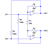
Here's an example of how you could implement synthesised loading resistance. Each op-amp has a gain of x9.2. R4 and R5 are each connected to outputs of inverted polarity, so the voltage across them is x10.2. Miller effect therefore means that the effective resistance seen looking into each input is 240k/10.2 = 23.5k, or 47k between inputs. But the current noise driven into the cartridge by the loading resistance has been reduced by a factor of square root of ten (because the resistor developing that current is ten times larger). The effect will be that less voltage noise will be developed across the (rising) impedance of the cartridge at high frequencies.
Unfortunately, the loading resistance isn't the only current noise source; all bipolar inputs have significant current noise, which is why I suggested a JFET. Agreed, when it comes to op-amps, most BiFET op-amps are >5nV/root Hz voltage noise. So you ideally make your own op-amp using a quiet JFET such as 2SK2145 or LSK170.
Incidentally, I tried making a low noise amplifier using some leaded LSK170C but I simply couldn't achieve the expected noise. Eventually, I fitted a pair of BF862 (from my very small stash) and the noise was immediately as expected from the JFET data sheet. I conclude that my LSK170C were fakes.
Attachments
Thanks for description.... One day I might try it, also order some OPA2828 from Mouser and make adapter boards (which I think would be good idea as group buy in any case). 3 nV (OP27) vs 4nV/sqrtHz (OPA2828) will not be observable.... Frankly I think nothing will be observable as all possible improvements are long time ago buried in LP surface noise 🤣
A cartridge termination resistor sits in parallel to the cartridge impedance.
That’s why any improvement of synthetic loading first starts to manifest itself in the kHz region because of the rising impedance of the cart’s inductor versus frequency.
After Riaa attenuation in the kHz region and after A-weighting the result will be a somewhat misleading ca. 3dB measured improvement in S/N, only caused by less HF content and not over the whole spectrum.
Hans
Hi Drazen,
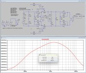
To show you the effect of synthetic loading on your design using the OP27 look at the images below.
The parameters from the OP27 are visible at the left and as such used in the op-amps.
Gain is 51.3dB or 367x, that's why I divided the A-weighted output noise by 367 to get the EIN, or equivalent input noise.
Since your first stage has a gain of 40dB, I used E4 and E5 to reduce this to 9x, so I could use 237K resistors for synthetic loading instead if the 23k7 that you use.
Since a Cart plays a vital role in the result of synthetic loading, I used 600R + 500mH for the simulation.
First image shows 47K loading, giving 494.8nV EIN, which for a 5mV@1kHz cart would mean a super good 80.1dBA S/N
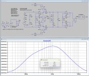
Second image shows the result after synthetic loading, resulting in 358.6nV EIN, resulting in a over the top 82.8dBA S/N
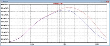
Third image shows the difference between both noise spectra, red with conventional loading an blue with synthetic loading.
So you gain 2.7dB in S/N , rather useless IMO from an already excellent S/N.
Hans
To show you the effect of synthetic loading on your design using the OP27 look at the images below.
The parameters from the OP27 are visible at the left and as such used in the op-amps.
Gain is 51.3dB or 367x, that's why I divided the A-weighted output noise by 367 to get the EIN, or equivalent input noise.
Since your first stage has a gain of 40dB, I used E4 and E5 to reduce this to 9x, so I could use 237K resistors for synthetic loading instead if the 23k7 that you use.
Since a Cart plays a vital role in the result of synthetic loading, I used 600R + 500mH for the simulation.
First image shows 47K loading, giving 494.8nV EIN, which for a 5mV@1kHz cart would mean a super good 80.1dBA S/N
Second image shows the result after synthetic loading, resulting in 358.6nV EIN, resulting in a over the top 82.8dBA S/N
Third image shows the difference between both noise spectra, red with conventional loading an blue with synthetic loading.
So you gain 2.7dB in S/N , rather useless IMO from an already excellent S/N.
Hans
Attachments
Dear Hans,
thank you for doing this! I see you even used exact values of C and R as in my final diagram. Thanks so much!
Your simulated values are extremely close to my measured values, within 1db or so, confirming simulation and measurement are both valid.
Dear EC8010,
I did not master synthesized loading technique myself, it is good to learn, thanks for that! Hans just proved that it works very well.
However it is pointless, design is already well above the target, no point to improve where there is no benefits that even in theory can't be heard by ears.
IMHO this preamp will satisfy all needs of bringing MM cartridges (as per today's technology of cartridges and vinyl records) signal to line level signal with high immunity to externally introduced noises because of high CMRR through fully balanced design,
This will not be observable device while listening,
By the way, my preamp is for MM, to accommodate any MC cartridge with negligible noise and also fully balanced noise rejection head preamp here is thread about it, little bit felt out of attention, but it is as good as it theoretically gets: https://www.diyaudio.com/community/...diff-in-diff-out-head-amp.322453/post-5428597
Cheers and thanks!
Drazen
- Home
- Source & Line
- Analogue Source
- Fully balanced MC phono preamplifier thoughts