Hierfi,
With 0.25mV input, you were expecting 4.3V out, true, that's a whopping almost 85dB gain, why so much ?
Anyhow, I had to make a number of adjustments to your proposal:
1) The collectors of the SSM's have a DC voltage on them, completely driving the AD844 into saturation.
That's why I inserted two 1uF caps into the lines and terminated them with 30K to Gnd.
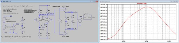
To keep the collector seeing 3K, I increased the original 3K to 3K33 (3k33//30K = 3K)
The the 43R between both minus inputs was way to low, so when going for a still very high gain of 80dB, this resistor had to be reduced to 270R.
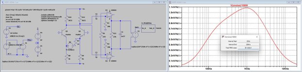
Now the FR was flat up to at least 100Khz, and A-Weighted noise referred to input was 61.4nV.
This brings the S/N for a 0.35mV/14R Cart at 20*Log(0.25mV/61nV) = 72.2dBA, not bad at all thx to the SSM's.
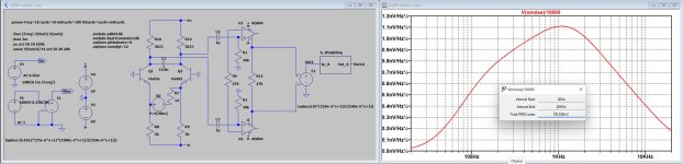
Changing the cap to the LTP collectors after precisely tuning for a flat FR, A-Weighted noise was now 79.5nV.
This brings the S/N to 20*Log(0.25mV/79.5nV) = 69.9dBA.
So while reducing the gain on the LTP, you loose 2.3dB.
Hans
P.S. There is still a lot of DC at the 844's current output, so when feeding these signals in output buffers, this has to be taken care off.
With 0.25mV input, you were expecting 4.3V out, true, that's a whopping almost 85dB gain, why so much ?
Anyhow, I had to make a number of adjustments to your proposal:
1) The collectors of the SSM's have a DC voltage on them, completely driving the AD844 into saturation.
That's why I inserted two 1uF caps into the lines and terminated them with 30K to Gnd.
To keep the collector seeing 3K, I increased the original 3K to 3K33 (3k33//30K = 3K)
The the 43R between both minus inputs was way to low, so when going for a still very high gain of 80dB, this resistor had to be reduced to 270R.
Now the FR was flat up to at least 100Khz, and A-Weighted noise referred to input was 61.4nV.
This brings the S/N for a 0.35mV/14R Cart at 20*Log(0.25mV/61nV) = 72.2dBA, not bad at all thx to the SSM's.
Changing the cap to the LTP collectors after precisely tuning for a flat FR, A-Weighted noise was now 79.5nV.
This brings the S/N to 20*Log(0.25mV/79.5nV) = 69.9dBA.
So while reducing the gain on the LTP, you loose 2.3dB.
Hans
P.S. There is still a lot of DC at the 844's current output, so when feeding these signals in output buffers, this has to be taken care off.
Attachments

When changing the 27K between the two AD44's into two 13K5 resistors, and connecting them to Gnd in between, The offset voltage of both AD844 outputs drops to -2.7mV on both sides.
All other things stay the same, FR and S/N, so this is an important addition.
Hans
All other things stay the same, FR and S/N, so this is an important addition.
Hans
Thanks Hans. In reality the AD844's operate with the inputs being DC offset if both are offset equally. It was designed for about 0.6 Volts positive given that the 3 kOhm resistance values are equal top and bottom, for power supplies being equal, and that the emitter voltages are always -0.6 volts. The difference in the upper voltage drop is just the lack of base current in the collectors, otherwise the voltage drops across the upper and lower resistors would be the same.
It doesn't make sense there would be net output current Hans. In the balance the +ve AD844 terminals are at equity when balanced (both at +0.6 volts), hence both -ve terminals would also be at equity, this in the absence of offset voltages. However the trimmer at the bottom of the 3 kOhms support adjustment of both the +ve terminals until the inverting terminals are set to equity (notwithstanding the +ve terminals are offset slightly to achieve this), hence no current flows between them. Although the current mirrors are not exact replicants of these inverting input currents, despite being laser trimmed, adjustments can be done to the mV levels in reality (being tested moments ago). The drift is fairly stable as well.
As far a gain goes, the gain is considered irrelevant, rather the intention is only to control the output headroom to maximize output signal drive. This is intended accomplished by the inclusion of the single controlling resistor R1, hopefully adjustable for any cartridge in a network perhaps below. In the case below the 50/500 network is current driven passive, hence has maximum overload headroom over the whole frequency range.
Last edited:
This lose is higher than expected Hans. This may be worse in reality, since the noise contribution is expected all high frequency because of the filtering... perhaps hiss. Though it sure looks tempting to use it anyway given the possibility of simplifying the network. Don't know if you would hear it anyway.Changing the cap to the LTP collectors after precisely tuning for a flat FR, A-Weighted noise was now 79.5nV.
This brings the S/N to 20*Log(0.25mV/79.5nV) = 69.9dBA.
So while reducing the gain on the LTP, you loose 2.3dB.
Another factor is that RFI might be reduced before feeding into the AD844's, hence value added above the audible frequencies (?). Although perhaps a 50kHz filter could be used instead at this location to perform that function.
Last edited:
My conclusion about avoiding DC on the inputs was when not having the the two 13k5 resistors connected to gnd in the middle.
Here are the results with and without the 1uF caps, and luckily both are performing the same, so the caps can be completely discarded.
You can see the identical collector voltages and AD844 output offset voltages, showing that hardly difference in offset occurs between both versions.
Hans
P.S. In case you wonder, the Mat02 is the same as the SSM2212.
Attachments
I still have some LM394's that I guess would be mostly the same as the Mat02. The SSM2220 pnp's are interesting at 0.7uV. I also have some THAT devices lying around somewhere... though I wish I had a little welder to weld some of those ZTX's together.
With regard to the movement of the capacitor to the LTP input side can it be simply that this capacitor no longer filters noise inherent to the AD844's above 2122 Hz? And potentially harmonic distortion components as well. This being no longer in the pre-RIAA area.
With regard to the movement of the capacitor to the LTP input side can it be simply that this capacitor no longer filters noise inherent to the AD844's above 2122 Hz? And potentially harmonic distortion components as well. This being no longer in the pre-RIAA area.
Last edited:
Yes, I can see, but why throwing away almost 3dB in S/N by inserting a cap in the SSM's collectors ?In the case below the 50/500 network is current driven passive, hence has maximum overload headroom over the whole frequency range.
Your previous design was more elegant IMO.
A strange thing is that with 10nF between the collectors, I can't get the 75usec pole right, obviously the AD844 inputs are starting to interfere.
That's why I kept the original 2*3K and 12.8nF.
The 3180usec and 318usec time constants were inserted in the current output, next to the 2*13,5K.
Gain is now 20dB lower at 60dB and overload margin is of course because of that 20dB higher..
Hans
Attachments
The LM394 is basically the same as the Mat02.still have some LM394's that I guess would be mostly the same as the Mat02. The SSM2220 pnp's are interesting at 0.7uV. I also have some THAT devices lying around somewhere... though I wish I had a little welder to weld some of those ZTX's together.
With regard to the movement of the capacitor to the LTP input side can it be simply that this capacitor no longer filters noise inherent to the AD844's above 2122 Hz? And potentially harmonic distortion components as well. This being no longer in the pre-RIAA area.
The Mat03 is the PNP version with only slightly less noise, don't expect a significant difference.
The cap in the LTP reduces the loopgain, thereby letting the noise from the AD844 make a larger contribution.
THD will increase also because of the same reason.
Hans
The correct values were also difficult to determine empirically. It might be because these resistors are in parallel with the collector resistances of the input pair, whereupon these devices are being operated at too low a voltage. In other words with higher operating voltages the poles could change... and the gain might go up as well (as perhaps also improving the S/N).A strange thing is that with 10nF between the collectors, I can't get the 75usec pole right, obviously the AD844 inputs are starting to interfere.
That's why I kept the original 2*3K and 12.8nF.
In principle I dislike throwing away any S/N in the audio band. Yet adding a smaller cap with a pole above the audio band can help to suppress RFI feeding into the AD844's without (hopefully) interfering with the S/N in the audio band.Yes, I can see, but why throwing away almost 3dB in S/N by inserting a cap in the SSM's collectors ?
The 3180usec and 318usec time constants were inserted in the current output, next to the 2*13,5K.
Gain is now 20dB lower at 60dB and overload margin is of course because of that 20dB higher..
The following shows a combination of all three poles in a current driven passive RIAA configuration. In order to keep the gain at about 0dB (as previously) the critical element is to begin with R1 equal to about 30K, with C1, C2 and the two R2's being determined from it. Of note is that if the positive power supply is increased to +8 Volts (as shown) the LTP will then operated with about 2.5 Volt drop, perhaps a better operating point (?) with increased gain and improved S/N (?). The problem in this design can be finding acceptable RIAA caps and of increased DC shifting in the output of the current conveyors. Of note is that the AD844's have offset controls that can handle minor offsets independently if DC servo control isn't used.

Last edited:
The intention is to provide gain programmability to 80dB+ (hopefully minimum 4 V RMS), this in conjunction with gain reduction adjustment via "R-gain" to support setting for best sonics.
Current conveyor voltage gain is related to current x (times) the resistance being fed. So it is that low frequency boosting requires a higher value resistance to be seen at the lower frequencies. Since gain of the 75uSec time constant has been determined in the previous network by the 2n77 capacitor in parallel with 27k Ohm, this identifies the target value that can be used to support 80dB+ gain at the highest frequency. Hence to boost the low frequencies by 20dB, going down from 500 to 50 cycles, requires increasing the resistance accordingly.
The change in resistance required is proportionately 10:1 to create the gain change required, whereupon the parallel combination must equal 27k when C2 shorts (since this reacts with the 2n77 C1 capacitor for the 75uSec pole). From the calculations the values become 270k in parallel with 30k (the R1 value you questioned), resulting in the parallel combination becoming 27k (from 270k). As in the previous network this 270k is split into 135k's around ground.
I included these values below. The value of C2 seems ought to be around 10.6 nF for the 50/500 time constants. Perhaps you can verify this. A caveat is that the R2 value is moderately high, that as a result the Rz of the AD844's, being in perhaps the 2 megOhm region, will create a lower equivalent resistance that will affect the 50 Hz pole to some extent, hence the value of R2 can require some increase to result in generating the required value.

From previous discussions regarding the variance from expected values for the 75uSec time constant, when capacitors are placed across the LTP, it occurred to me that the transistors may not be operating on the flats of the curves, as exampled below. Although this doesn't necessarily reflect the reality it questions if the voltages across the LTP devices ought to be higher than 0.6 volts to seemingly eliminate impedance contributions of the collectors by operating the transistors more on the flats. Collector voltage variations don't affect the collector currents on the flats, hence appear as an infinite impedance. This may also be important from an RFI rejection perspective. I also added a 220pF capacitor across the collectors to filter frequencies above about 100 kHz (RFI?). It seems that this value would not deteriorate the noise immunity in the audio band significantly, if even noticeable.

Current conveyor voltage gain is related to current x (times) the resistance being fed. So it is that low frequency boosting requires a higher value resistance to be seen at the lower frequencies. Since gain of the 75uSec time constant has been determined in the previous network by the 2n77 capacitor in parallel with 27k Ohm, this identifies the target value that can be used to support 80dB+ gain at the highest frequency. Hence to boost the low frequencies by 20dB, going down from 500 to 50 cycles, requires increasing the resistance accordingly.
The change in resistance required is proportionately 10:1 to create the gain change required, whereupon the parallel combination must equal 27k when C2 shorts (since this reacts with the 2n77 C1 capacitor for the 75uSec pole). From the calculations the values become 270k in parallel with 30k (the R1 value you questioned), resulting in the parallel combination becoming 27k (from 270k). As in the previous network this 270k is split into 135k's around ground.
I included these values below. The value of C2 seems ought to be around 10.6 nF for the 50/500 time constants. Perhaps you can verify this. A caveat is that the R2 value is moderately high, that as a result the Rz of the AD844's, being in perhaps the 2 megOhm region, will create a lower equivalent resistance that will affect the 50 Hz pole to some extent, hence the value of R2 can require some increase to result in generating the required value.
From previous discussions regarding the variance from expected values for the 75uSec time constant, when capacitors are placed across the LTP, it occurred to me that the transistors may not be operating on the flats of the curves, as exampled below. Although this doesn't necessarily reflect the reality it questions if the voltages across the LTP devices ought to be higher than 0.6 volts to seemingly eliminate impedance contributions of the collectors by operating the transistors more on the flats. Collector voltage variations don't affect the collector currents on the flats, hence appear as an infinite impedance. This may also be important from an RFI rejection perspective. I also added a 220pF capacitor across the collectors to filter frequencies above about 100 kHz (RFI?). It seems that this value would not deteriorate the noise immunity in the audio band significantly, if even noticeable.
I’ll give it a try today.
Gain with this topology can be set in two ways, with the resistor Rg between the minus inputs and with the Riaa network.
There must be an optimum somewhere, so I’ll try with three sets of Riaa networks and adjust Rg accordingly to get the same gain in all three versions.
The resulting FR and S/N should give a clue about a possible optimum.
Hans
There is an interesting variance that I was thinking about this morning that seems can better realize the optimum. The configuration is as follows

Given the current conveyor connection of the AD844's, the output amplitudes can be reduced in absence of adjusting Rg1 by reducing the resistance values. In the circuit above the RIAA resistance values have dropped by an order of magnitude, consequently the capacitors have increased by that amount. By adding a x10 gain network the result is that the output levels are comparable to the previous network. It is expected that S/N values would be comparable (as Rg1 hasn't changed). Of note too is that because the R2 values are reduced by 10x this reduces the influence of the Rz values being paralleled inside the AD844's from affecting the 50 Hz pole.
In the previous network the gain reduction is performed by Rg1. It is expected that increasing Rg1 to reduce the output level deteriorates S/N overall, expectedly much like adding emitter resistance in a moving coil head amp. In the above network gain can be reduced instead by Rg2, a location that isn't expected to deteriorate noise performance. This leads to the conclusion that Rg1 should be 0 Ohms for best S/N, hopefully that doesn't then overload the modified RIAA network being reduced of gain to 1/10. In this network gain adjustment would be limited to 1/10th by the removal of Rg2.
An aspect that warrants mentioning, and perhaps investigated, is the extent of the current drive into the RIAA network. As this is a mirrored value of the inverting terminal current this can be monitored by replacing Rg1 with perhaps a 1 Ohm resistor and observing the resultant voltage waveform across it.
Last edited:
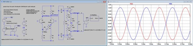
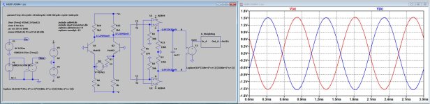
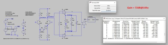
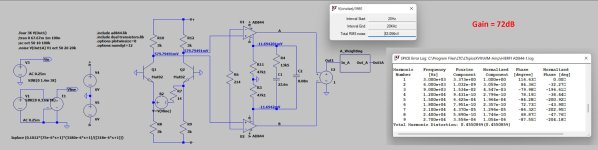
I simulated two versions, both with a Gain of 72dB to keep some headroom left, an arbitrary value choosen because the Cart's 0.25mV@1Khz is at -72dB.
Since the complete Riaa network is within the AD844, I could now use the existing AD844's output buffers.
After having meticulously adjusted the FR to be within 0.05dB, I measured from both versions the A-Weighted noise and the distortion at 1mV@3Khz.
From both versions can be seen that the A-weighted noise is the same at 72dB, but the THD worsens for a lower Rg value.
I had in mind to test a third version with an even lower Rg value, but given the increase in THD, I stopped at this point with just two versions.
Hans
Attachments
Interesting results Hans. Using the AD844's internal buffers is interesting. I have wondered about its distortion contribution given the dynamic current source drive. If the simulators measurement circuit shown as Out1 E2 in Current 7 is high enough impedance can this be attached to the RIAA network directly in absence of the output buffer so the distortion contribution can be compared to that being shown above?
By the way, thanks for the meticulous adjustments to set the FR so accurately. This may allow for simplistic scaling for alternative values.
By the way, thanks for the meticulous adjustments to set the FR so accurately. This may allow for simplistic scaling for alternative values.
I did compare, but it makes absolutely no difference in distortion.If the simulators measurement circuit shown as Out1 E2 in Current 7 is high enough impedance can this be attached to the RIAA network directly in absence of the output buffer so the distortion contribution can be compared to that being shown above?
Hans
Yes that’s the effect of differential signals.
Even harmonics cancel each other.
But in this case it’s quite extreme because all tolerances are zero.
In real life this won’t be that extreme.
Hans
Even harmonics cancel each other.
But in this case it’s quite extreme because all tolerances are zero.
In real life this won’t be that extreme.
Hans
So. I'm reading right, but definitely writing wrong... Reading, not riding🤣.
Thanks Hans, you read what I meant anyway
Thanks Hans, you read what I meant anyway
The tests were interesting and confirmed some of my suspicions. Thanks for doing them Hans.From both versions can be seen that the A-weighted noise is the same at 72dB, but the THD worsens for a lower Rg value.
I had in mind to test a third version with an even lower Rg value, but given the increase in THD, I stopped at this point with just two versions.
One of the conclusions drawn is that in order to better control distortion at high output signal levels, the RIAA impedances need to be as high as possible, perhaps to the point the A-weighted noise begins to go up. Perhaps values for C1 being in the 4n7 or 5n6 region (ones I have), being almost half of that below. Increasing the impedance reduces the current drive necessary to support higher output amplitudes, this being the mirror current that was caused to flow in the inverting terminal.
As suggested by your testing, to reduce distortions the Rg value needs to be high, seemingly in relation to the Ro values of the AD844 inverting terminal. Ro's values become more prevalent as Rg reduces, however of being balanced logarithmic in variance being driven by voltages developed across the input 3 kOhms, hence the reason for seeing the dominance of odd harmonics increasing with the lowering of Rg.
One mechanism of reducing such distortion can be to introduce a gain element between the input LTP and the AD844 to increase the voltage levels applied to the +ve input terminals, whereupon Rg can then be increased to achieve the same output as above. Although the RIAA values were not the same as yours above I tested using a matched 2n5542 jFET device (one at my disposal) for functionality, being connected as a simple moderate gain differential interstage amplifier as per below. In the figure below I kept the RIAA values the same as yours to simply the comparison of S/N and distortion if you would care to do them Hans. I would be interested in the result.

Last edited:
- Home
- Source & Line
- Analogue Source
- Fully balanced MC phono preamplifier thoughts