No matter how you internally configure your MC Phono amp, at the end you will need => 60dB gain at 1Khz and a satisfactory S/N.Post passive RIAA typically requires significantly more headroom (as evidenced in this thread) because of the boosting of high frequencies. This headroom isn't nearly as problematic when using current mode output driving a passive RIAA as the resistive element is grounded as per below.
Either using a current driven or a voltage driven passive Riaa network does not bring any principal advantage.
Hans
The advantage is in the pre-RIAA Hans. The network recently completed contains a current magnification stage before feeding the RIAA. This is something I am continuing to experiment with. Notwithstanding what happens at the end, the issue can be considered related to managing both voltage and current overload in the pre-RIAA feeding the passive network.
Ultimately the idea is to reduce impedances, as noise and resistance are closely tied. It seems that in order to do that, and maintain signal levels, is to increase the power drive. This is all speculative but fun.
By the way the nicest analog system at the Toronto AudioFest show contained a cartridge costing $18,000. At a life expectancy of 1000 hours I suspect you can buy records for less cost than it costs to play them once.
The following network provides adjustable current gain mechanism and dramatically improves voltage overload margins, rather being alternatively dependant upon the ability to drive current directly into the output capacitances.
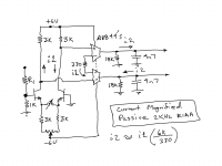
In the testing the network was first subjected to a 1KHz/ 5 cm/sec record test signal producing about 1.9V RMS output. Of note is that the supply voltages of the AD844's were reduced to only +/-5 Volts, resulting in a condition of overload at only about 2.2V RMS or about 1.3dB overload margin, effectively no overload margin.
With the stylus lifted a signal generator input signal was provided to the input of R1 in a divider that for a 1.9V RMS output signal at 1 KHz required an input signal from the generator of about 1.6 V. This establishes the reference point for evaluating high frequency output overload margins. In the testing below the frequencies were increased accordingly whereupon the input amplitude was increased to still result in a sinusoidal 1.9V RMS output signal, indicating the ability of the network to handle input signals short of overloading.
1KHz 1.6 Vin. 1.9 Vout
4KHz. 3.2 Vin. 1.9 Vout
10KHz 7.6 Vin. 1.9 Vout
20KHz 14 Vin. 1.9 Vout
This indicates that this form of network can handle about 19dB input signal increase at 20KHz relative to 1KHz, albeit at a dramatic increase in current to charge the 4n7 capacitors. Notwithstanding that the network can handle such signals more easily the provision of a gain setting resistor permits adjustability for improving overload margins or adjustment for variant cartridges. As an aside there is no longer any clipping observable when playing the O Superman cut.
In the past I worked a lot on so called TCO (Total Cost of Ownership) model, where interest was to prove total cost (purchase, installation, utilities consumption, waste creation, operator utilization and probably some more factors) to potential buyers of industrial equipment , showing total cost of multi million bucks equipment from moment of down-payment to poit of sending it to recycling. Guess this 18,000 cartridge will score close to maximum waste of money in that calculation, just hope whomever buys this and spends 18,000 on annual (or bi-annual, as those guys usually don't listen anyway) for LP listening cost, also spends minimum 180,000 on charity.By the way the nicest analog system at the Toronto AudioFest show contained a cartridge costing $18,000. At a life expectancy of 1000 hours I suspect you can buy records for less cost than it costs to play them once.
PS, when I bought high end cartridge that I have and is now worn out apparently, I was manager in Zurich and really had a lot of funds.
My thinking was ok , now I'm 36 or something, loaded, lets do something expensive. Everyone in office had those swiss watches, so why not, minimum 4000 for Schaffhuser, lets add 3000 for ring for my babe!. Than I thought what really matters in life, bought myself BM Ruby 2 for less than half ow watch, and 1/2 karat earnings for GF, saving was I think about 3 or 4000, and that went to help those who actually need it, both GF and myself were much more happy with gifts we got than with unneeded luxury. (nobody says that what we got is not luxury, it is, I'm bit ashamed for past sins)
My thinking was ok , now I'm 36 or something, loaded, lets do something expensive. Everyone in office had those swiss watches, so why not, minimum 4000 for Schaffhuser, lets add 3000 for ring for my babe!. Than I thought what really matters in life, bought myself BM Ruby 2 for less than half ow watch, and 1/2 karat earnings for GF, saving was I think about 3 or 4000, and that went to help those who actually need it, both GF and myself were much more happy with gifts we got than with unneeded luxury. (nobody says that what we got is not luxury, it is, I'm bit ashamed for past sins)
Could you please add a complete Riaa network including the 3180usec and 318usec time constants.This indicates that this form of network can handle about 19dB input signal increase at 20KHz relative to 1KHz,
This will change things.
Hans
Hi, on HF headroom margin;
Today I reminded myself of this article by good and down to earth Rod Eliot: https://sound-au.com/project06.htm . He also has a view that it is not so of an issue at all.
Also somewhere in this thread I posted an idea, no reaction on it as it could be nonsense or bag of worms (even I like worms, I like fishing and they are good for that 🙂)
Here is idea again: to put HF cut directly in the tails of first Long tail pair. If it works it will be reduced close to source.
Sure Hans. Although most things have remained the same, the network below is a tentative variant of a previous network completed that reorients the RIAA networks. In the network below the supplies to the AD844's are increased to +/- 15 Volts to increase the voltage headroom. For the 3180usec and 318usec time constants the idea is to set the gain of the NE5532's to a gain of 10 at low frequencies, whereupon high frequency gain becomes unity when C4 shorts. If the power supplies of the NE5532's are equal to that of the AD844's the overload ought to be similar for high frequencies... if in isolation from any low frequency content being amplified by the NE5532.Could you please add a complete Riaa network including the 3180usec and 318usec time constants.
This will change things.
Hans
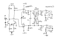
In the first iteration the plan is to set the 1KHz 5cm/sec output level to perhaps 4 V RMS which ought to be close to that internally and see what happens sonically. By the way, I added the DC servo's to indicate the simplicity that this can be achieved in the current mode, it loops unto itself. One other thing, I used 0.1 % 3 KOhm resistors to keep the inputs well matched to maximize the CMRR on the inputs.
DrBulj... rejection of RFI and other unwanted high frequencies is oftentimes critical in amplification of low level signals. Numerous networks, including the one shown can help... if they don't themselves cause sonic issues (or instabilities). By the way... I have been experimenting with capacitors across the positive input terminals of the AD844's to create a common mode voltage to inhibit current flow through the 330 Ohm resistor at high frequencies.
Last edited:
Dear Hierfi, I'm totally lost at first with above diagram, might be I'm not up to level..... OK, if I think current and forget volts, servo's seem functional. But how can opamp (5532) feed 10ohm?
On this one I did not have RFI attenuation in mind, but 75us HF pole of RIAA, much deeper cutDrBulj... rejection of RFI and other unwanted high frequencies is oftentimes critical in amplification of low level signals. Numerous networks, including the one shown can help.
Sorry... I was not being very clear... likely to anyone else.
It was meant as a generic R... not as an actual ohmic value. In other words they are ratio-metric to each other, one being 9x greater than the other at 1x. For example one resistor is 1kOhm and the other 9kOhm, and whereupon C4 is of value such that the resultant is to create 3180usec and 318usec time constants
It was meant as a generic R... not as an actual ohmic value. In other words they are ratio-metric to each other, one being 9x greater than the other at 1x. For example one resistor is 1kOhm and the other 9kOhm, and whereupon C4 is of value such that the resultant is to create 3180usec and 318usec time constants
Well, step by step it is becoming a real (hybrid) solution.Although most things have remained the same, the network below is a tentative variant of a previous network completed that reorients the RIAA networks.
As a suggestion, you could just as you did with C1, use one resistor between both AD844 outputs and also for C2 and C3.
I made a quick simulation showing the FR of your design,
Input is 0.6mV@1Khz in green and output is 3.5Vrms in red.
The blue line shows the signal at the output of G1, the voltage to current converter.
When you give me component values of your design in detail , I can sim the FR with the AD844's and calculate the S/N.
Hans
Last edited:
I like this. Even admitibly still grasping the design, above I'm sure off, whenever differentials are in play, avoid touching ground except for ref voltage.As a suggestion, you could just as you did with C1, use one resistor between both AD844 outputs and also for C2 and C3
Well, step by step it is becoming a real (hybrid) solution.
As a suggestion, you could just as you did with C1, use one resistor between both AD844 outputs and also for C2 and C3.
I made a quick simulation showing the FR of your design,

This looks good Hans. I haven't done any simulations since my Windows 2000 machine died, hence verifying my questionable expectations and/or beliefs, and particularly determining the correct RIAA values is of valued assistance. Thanks. I should mention that the actual values to be decided upon will be dependant upon teflon capacitors at my disposal, being of rather loose tolerances at that. Hence resistors will be used to set and tighten the RIAA tolerances. The largest I have are 47nF's, with 22nF's being physically smaller and therefore easier to implement.
The outputs of the AD844's are both current conveyors, hence aren't yet referenced to any fixed voltage or ground. Hence even minor non-symmetric difference currents will cause a voltage drop across the common Rz's of the devices, being perhaps 3-4 megOhm each. To make the implications of current conveyors more clear the following shows how a current conveyer can modify the set point reference, with signal currents appearing balanced around this point, yet no current flows through the 10 kOhm below in the ideal case. In other words the outputs can be shifted to values off ground, that if alternatively grounded forms an ideal reference point for output signals. This is to suggest this point seems best grounded for the operating manner of these conveyors.
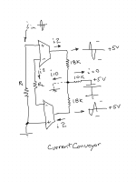
In retrospect there seems an advantage in removing ground from the output 50/500 Hz RIAA output network, using instead a single resistor R3 between the inverting terminals, whereupon the current conveyor reference ground becomes virtually connected to the output 50/500Hz RIAA networks. This looks basically like the following, using values derived from your previous analysis. Hopefully these are correct.
Hierfi,
1) What about the long tailed pair in front, discarded ?
2) Should your target amp has a voltage or a transimpedance input
3) What are resp. output voltage and resistance of your Cart.
Hans
1) What about the long tailed pair in front, discarded ?
2) Should your target amp has a voltage or a transimpedance input
3) What are resp. output voltage and resistance of your Cart.
Hans
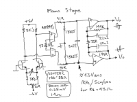
The network below was adjusted by R1 to produce about 4 V RMS at the current conveyor output. This is close to the gain limit of the AD844's given the addition of the Ro's (about 50 Ohms each) of the inverting terminals being in series with R1, hence the total is about 143 Ohms effectively. It should be noted however that gain can be increased by increasing the values of the output resistors, hence also using a smaller capacitance for the 75uSec pole. Another alternative is to stack AD844's to also reduce interstage noise and increase current drive.
Note that the 91 Ohm resistors are normally added in series with pin 5 of the AD844's for stability purposes, the value being somewhat arbitrary to support this objective. The network uses a 2.77 nF capacitors for the 75uSec pole as I have such capacitors, with resistors adjusted accordingly. The output values have been changed to reflect capacitors available, specifically the 22n1 values, though I haven't yet constructed this network. Although I am currently using the SSM2212, the PNP version could be substituted in a network inversion as having lower noise.
The cartridge used is the Denon 103R is 0.25mV / 14 Ohm. I am not sure what you mean by target amplifier.

Last edited:
As an aside Hans, I conducted an experiment (albeit risky) tying the +ve terminals of the AD844's to ground and applying the Denon 103r directly between the inverting input terminals. This yielded about 50mV RMS for 1 KHz 5 cm/sec, indicating that the inclusion of the SSM2212 input pair causes the gain to increase about 38dB in this configuration. The conclusion being that the noise contribution would be mostly dominated by the SSM2212 input pair.
Hi Drbulj. My concern was that it reduces the already low level signals above 2122 Hz. Meaning that subsequent circuit noise can pose a problem by the reduction of these signal levels in relation to whatever noise exists in the amplification device that follows it. In retrospect this may not be as significant as first thought given the experiment conducted in post #558.
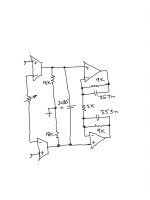
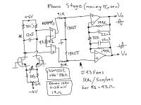
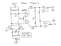
Though not identical to your diagram, a capacitor can be placed across the collectors that interacts with the 2x 3k Ohm load resistors to form this 75uSec pole. In the calculation the value seems about 12n5 given the 3 kOhm load resistors. For direct comparison purposes (if Hans wants to do this), this pole can be moved to that shown on the left below without changing other components of a network he is planning on simulating. If this works out this provides an opportunity to move the 50/500 Hz poles into the current conveyor location as shown on the right. This can simplify and seemingly improve the network. By the way, the input was already changed to support the use of a 10nF capacitor for the 75uSec time constant.
Last edited:
Thank you Hierfi!Hi Drbulj. My concern was that it reduces the already low level signals above 2122 Hz. Meaning that subsequent circuit noise can pose a problem by the reduction of these signal levels in relation to whatever noise exists in the amplification device that follows it. In retrospect this may not be as significant as first thought given the experiment conducted in post #558.
Though not identical to your diagram, a capacitor can be placed across the collectors that interacts with the 2x 3k Ohm load resistors to form this 75uSec pole. In the calculation the value seems about 12n5 given the 3 kOhm load resistors. For direct comparison purposes (if Hans wants to do this), this pole can be moved to that shown on the left below without changing other components of a network he is planning on simulating. If this works out this provides an opportunity to move the 50/500 Hz poles into the current conveyor location as shown on the right. This can simplify and seemingly improve the network. By the way, the input was already changed to support the use of a 10nF capacitor for the 75uSec time constant.
My thinking is that HF (above 2122 HZ ) is recorded too high by RIAA, somewhere we need to cut 20db from it, and if done soon enough, irrelevant problem (i think it is not so relevant) of HF headroom will go away for good.
I like your sketch on the right a lot, even wondering if in such schematic is there any more point of current pumps, why not just LM4562 or NE5532 or NJM2068, just usual stuff? Also think, but not much important in this stage, last 2 opamps should have some gain and in differential mode, waist to use them only as buffers.
Cheers,
Dražen
- Home
- Source & Line
- Analogue Source
- Fully balanced MC phono preamplifier thoughts
