I put them at the end, after second stage 🙂AC coupling capacitors to passive RIAA correction networks can have a rather similar effect.

Nice work from Dicks! Thks for pointing out.Buy a bunch of ZTX851 and select for matching pairs - on each side the matching doesn't have to be great, just between the two sides. Should get to 0.223nV/√Hz - however with a single ended preamp you'd get 0.158nV/√Hz with half the number of low noise transistors, or 0.112nV/√Hz with the same number - balanced circuitry is inherently sqrt(2) noisier than single-ended all else being equal... Anyway its possible to get very low voltage noise with ZTX851 / 951 or similar devices, far better than the AD797 alone for instance. See this link: http://www.dicks-website.eu/low_noise_amp_part3/part3.html
My mistake, I did not mention before that I'm using Ruby 2 naked cartridge. Benz Micro recommends ideal load at 1kohm, not usual 100ohm.
Looking at Dicks test setup, input Z is close to nothing, would this mess up the cartridge? Or you had LTP circuit in mind?
Im aware of some balanced downsides, but upsides are great, compromises as usual...
A pair of ZTX devices in a transimpedance configuration is about 4x quieter than an AD797 in an MC amplifier application. With discretes however you need quite a bit of additional circuitry around the devices if you want to make it foolproof and/or avoid large input coupling caps.
I played around with a balanced input MC amp a few yrs back (‘TranBal’ on this site somewhere’) that simmed with excellent CMRR and very low thermal noise of c. 400 pV/rt Hz which is about half that of an AD797. I did a board and started preliminary testing etc but, at the end of the day I decided the additional complexity and effort for what were potentially marginal gains only in CMMR over the X-Altra MC/MM were not worth it. YMMV
I played around with a balanced input MC amp a few yrs back (‘TranBal’ on this site somewhere’) that simmed with excellent CMRR and very low thermal noise of c. 400 pV/rt Hz which is about half that of an AD797. I did a board and started preliminary testing etc but, at the end of the day I decided the additional complexity and effort for what were potentially marginal gains only in CMMR over the X-Altra MC/MM were not worth it. YMMV
Thanks Bonsai! Pity you did not finished it. If you wish you can continue here and help me and might be others. I will surely build one soon.
I am just discovering these ZTX transistors, seems like gem, not only ultra low noise, but also high Ic and Vcbo, this could be used as VAS stage for mosfet outputs too. But another time......
See couple of comments "if balanced is worth effort". Well, one DIYer will hardly spend 150€ on any material for whatever RIAA preamp (unless buying unobtainable and /or snake oil). My cart cost me 1,500 Euro, (today similar ones are over 3000) That makes my preamp 10% cost of cartridge.
If I add turntable in worth of 4000 - 5000, my preamp is 2% of value, now add 200 new LP's and preamp is 1% of TT fun cost. My pure business management logic tells me that it is worth to invest in preamp whatever it takes (within common sense and diy).
Tonight Ill try to make an generic drawing of summary what was told here so far, to facilitate discussion and to be used as playground.
Cheers till then,
Drazen
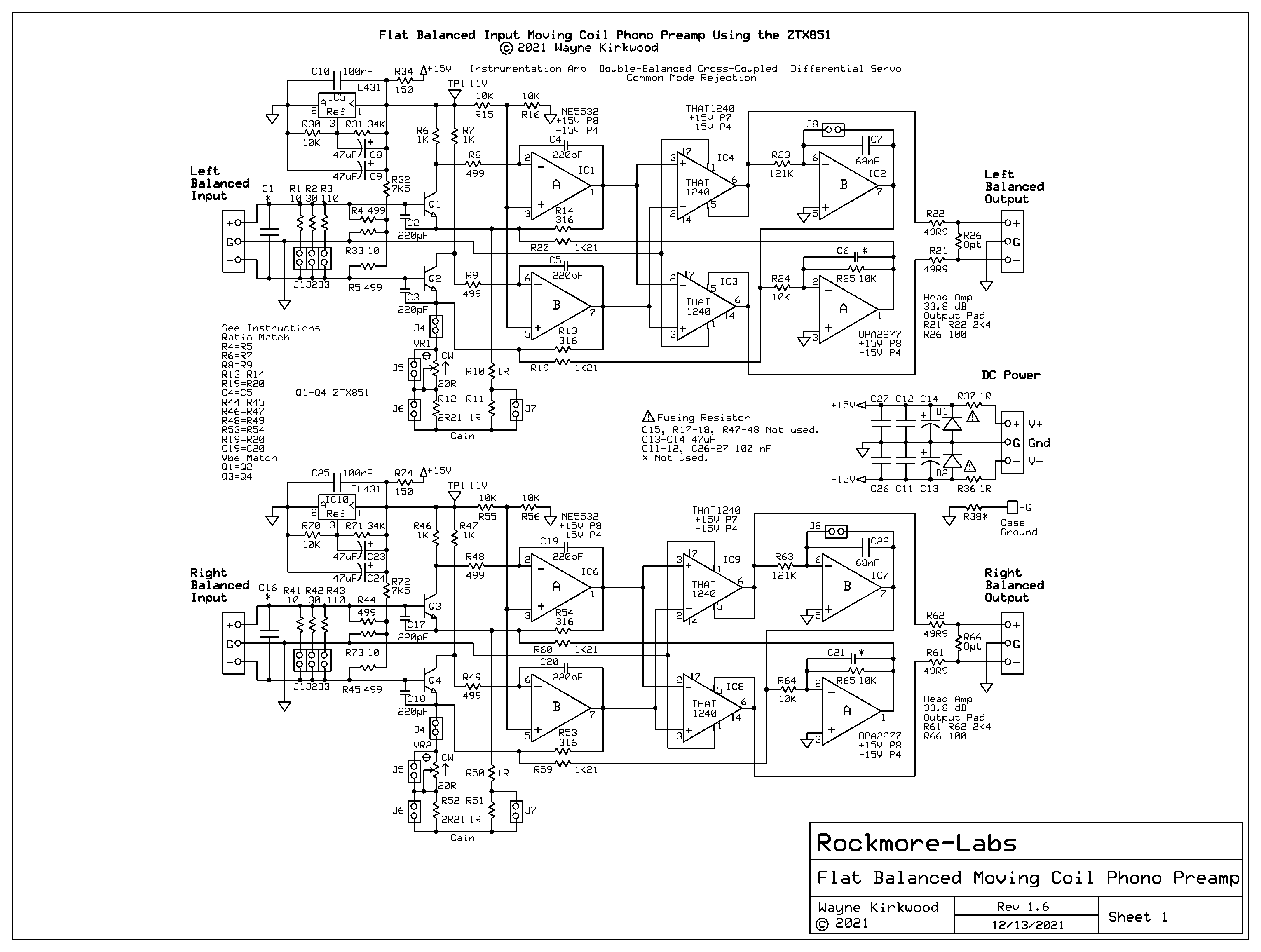
Dears, here is roughly one layout, just as playground.
It is fully differential, but if one draws GNDA line from where it is to the right and left, and deletes everything below it, then it is single ended.
The PCB in the end can be made a) balanced as is below, or b) stereo if one ground line is added.

Please comment if you wish to participate, cross, delete or change whatever you see fit:
Here are my thoughts when drafting this, pls challenge at will:
Looking forward!
It is fully differential, but if one draws GNDA line from where it is to the right and left, and deletes everything below it, then it is single ended.
The PCB in the end can be made a) balanced as is below, or b) stereo if one ground line is added.
Please comment if you wish to participate, cross, delete or change whatever you see fit:
Here are my thoughts when drafting this, pls challenge at will:
- LTP input instead of current as we are not sure of cart impedance. I'm not even sure what my Ruby 2 has, but they recommend 1k load.
- Q1, longish list: ZTX, BCm53, 2sk1541 just mentioned, I can add MAT + SSM matched pairs (if they still exists). Both NPN and PNP can work here (with turn around diagram). Q1A and Q1B must be matched as bunch.
- As example I put 2mA current per device as it seems to fit.
- U1 will see very low input impedance, so no need for jfets, as example I installed LM4562 here as quite standard opamp
- RIAA network; R1, R2, C1, C2. For C I think Polystyrene is right way
- U2 will see R1 as source resistance, so I put JFET OPA828. RMS signal here will be nominal 34mV, so I guess its input noise will not be of big issue here.
- For above to work good, most of the resistors need to be 0.01% or carefully matched pairs
Looking forward!
Forgot to mention;
JFET's for Q1?? probably more difficult to match than BJT's ?
Unless expensive matched pairs are used.... To contradiction of my own words in post #25; I'm not sure that approx 120 Euro for 12 LSK matched pairs is worth it???
JFET's for Q1?? probably more difficult to match than BJT's ?
Unless expensive matched pairs are used.... To contradiction of my own words in post #25; I'm not sure that approx 120 Euro for 12 LSK matched pairs is worth it???
Build the ribbon mic preamp from Art Of Electronics ed3. (book by Hill /Horowitz)
70 pV/rtHz , works as promised. I have built a single ended version
with 1/4 the number of transistors and a whole bank of input capacitors.
Most interesting signals are NOT centered around 0V.
No need to match transistors. That seems to be an audio boy fetish.
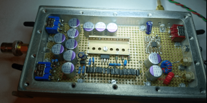
The box was RF stuff from ebay. It gained worth by making it empty.
Methinks I have written more on it somewhere else on this site.
70 pV/rtHz , works as promised. I have built a single ended version
with 1/4 the number of transistors and a whole bank of input capacitors.
Most interesting signals are NOT centered around 0V.
No need to match transistors. That seems to be an audio boy fetish.
The box was RF stuff from ebay. It gained worth by making it empty.
Methinks I have written more on it somewhere else on this site.
Attachments
LTSpice accurately predicts thermal noise performance on discrete designs if the models are correct so I would encourage anyone looking to design low noise preamps to look into this.
Hi Bonsai,
Yes, sure, and I did. This is roughly what I'm using for quarter of century. At beginning of this thread is my turntable thread where I detailed the rest; https://www.diyaudio.com/community/...eded-with-motor-and-drive.412984/post-7687982
This topology is more than satisfying, noise is not practically hear able and it is very immune to external influences, very robust solution. The idea was (as Im opening TT for motor and drive upgrade) to revisit preamp and make use of community knowledge to do it as good as possible. Fully differential has robustness and CMRR merits ..
Build the ribbon mic preamp from Art Of Electronics ed3. (book by Hill /Horowitz)
A pair of ZTX devices in a transimpedance configuration is about 4x quieter than an AD797
Hi,
I looked a bit more into transimpedance solutions and cartridge loading questions (Art of Electronics and here http://www.hagtech.com/loading.html) , not through the study yet. If I did not get it wrong, current (transimpedance) amp relays on extreme low source resistance. I think it is worth asking a question:
How is different carts source Z (inductance and resistance) influencing such low Zin amps? Is this to worry about?
Usually loading cart to high is not making fantastic sound...
Cartridges are not made the same! This is a bit trivial statement as it can be applied for anything 🙂, but it is true, many MC cartridges go as high as 100 Ohm.
My idea was to make best diagram that could fit most of high end low out MC-s, for everyone's taste (and budget)
Here is spec of my cartridge as example; 45 ohm source resistance, inductance not specified :-(
(PS, love handwritten, paper roll, test measurement paper, so Swiss)
Drbulj,
In a transimpedance amplifier, the MC cart effectively runs into a short. The cart works like this because in this mode it is being used as a current sensor and not a voltage sensor. You can do this because the cart series resistance is low and the relative currents are quite high (10's of uA). The advantage of this topology is that the only active contributor to noise is rbb' which on transistors like the ZTX851/951 is about 1.4 Ohms each. And if you use a complimentary input stage a la Marshall Leach/Richard Lee/X-Altra MC/MM, the two rbb' appear in parallel, so the total effective rbb' noise is further reduced because the noise sums stochastically.
Your Ruby cart has quite a high internal resistance. I am using a DL103 with my X-Altra MC/MM with the cart test certificate showing 390uV output and I measured the pickup coil resistance at 30 Ohms.
A SE input has zero CMRR, a differential input can easily achieve a high CMRR.Any evidence for an advantage out there?
A Cart is a perfect balanced source.
As long as the overall S/N with Cart connected including the additional 3dB diff. noise penalty is still high enough, this extra noise won’t have any impact.
Hans
- Home
- Source & Line
- Analogue Source
- Fully balanced MC phono preamplifier thoughts