Yes, this mid is misbehaving when it comes to directivity and FR, remember the cardboard tests earlier in the thread? 😉 I actually have a pair of dust caps on the way that I want to try to stick on to see what happens. As it is now, any EQ I apply on the mid just seems like a bad compromise, so I might be better off without all the EQ attempts, that's why I want to try the simplistic approach too. Come to think of it, I should measure the second mid and compare them..
The waveguided tweeter is better, some bundling, but good enough for me I think.
Actual final listening position will be within a couple of degrees from 0, so whatever my ears can make of the last octave should be there 🙂
From earlier experiments, I think my preference was lower order slopes with moderate amount of linearization to the drivers responses before the XO slopes were applied. However, back then I was only measuring on axis, and a few occasional off axis measurements as a 'sanity check'.
My measurements might not be the best.. I measured the mid box separately, so there could be some influence from the bass box when it's sitting on it. I did however make two sets of measurements on separate occasions, and they did seem to match pretty well. I should however run some simple measurements on the complete speaker with filters applied to see that it is similar to the sim.
Yeah you seem to have good handle on things so explore away 🙂 If you want help you can post the VituixCAD project with measurement data here and people might have a go at it, at least vineethkumar did so in his 3way study thread and several members posted versions to try out. If I remember some measurement problems were spotted and new tricks learned if nothing else.
I just had a look at that, and 'file/archive project' is greyed out for some reason, not sure why..
I even tried to zip the relevant folders, but that turns out to a 26MB zip, don't think I can upload that on the forum..
I even tried to zip the relevant folders, but that turns out to a 26MB zip, don't think I can upload that on the forum..
When I first started measuring speakers, I had difficulty capturing accurate phase response between drivers. In other words, I had an unknown time delta (time error) between the drivers.
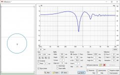
Rather than start from scratch and redo all the polar measurements, I found a way to salvage the data. An LR4 crossover with reverse polarity will produce a very deep, very sharp null. The depth of the null is very sensitive to timing, which makes it a useful tool
I first made a Vcad sim with LR4 reversed polarity, and adjusted the time delta to produce the maximum possible null. This is "sim time delta"
Next I loaded the same crossover filter into the DSP, made a frequency response measurement. I adjusted the actual time delay until I produced the deepest measured null. This time delay is "DSP time delta"
The time error is difference between the two delays. Time error = (sim time delta) - (DSP time delta)
Now I know I have to incorporate the time error into the DSP filter so that it matches the Vdad sim. Even if my subsequent filters are not LR4, the time error stays constant.
You might find this a useful technique.
j.

It does not take much delay to screw up measurements at high frequencies. At 3 kHz, the wavelength is 114 mm. A 45 degree phase error is just 14.5 mm... If the mic position or speaker position is allowed to vary by 14.5 mm, you will get a 45 degree phase shift error.
This evening I have been working on the most complex XO-version, with LR4.
I found a very easy way to import the biquads from Vcad. Just mark all for one driver (using ctrl to select many), copy parameters and paste to text file, and import the text file to the minidsp, -done! With channels linked in minidsp, the same biquads are applied to both channels. I used biquads for XO slopes and all corrections. Only delays and gains are left to adjust manually in the minidsp.
Gains are an issue though, since different amps will probably be tested etc. and they will differ in gain.
I did the offset/delay checks, and mid to tweeter was close to sim/measurements. Mid to woofer puzzled me for many reasons, I ended up doing it by looking at the impulse response to find the delay (mic placed halfway between drivers). Delays are now 0.55ms mid/woofer, and 0.03 mid/tweeter.
Another confusing thing was that I had to use different polarity between woofer and mid to get summation with LR4, and that does not seem right to me? Maybe there is something going on with cables or amps, I have not investigated everything yet, but I could see a null around XO when they were the same polarity in minidsp. Mid/tweet LR4 is summing well with same polarity.
Had a friend visit in the garage, and he thought they sounded big, and I guess he's right. The LR4 version sounds pretty good now, but I need to add some slope to the FR, pretty close to flat as it is. It gets hard to prioritize when I want to tinker/measure and listen to music from the speakers at the same time.. 🙂
Been having some fun, and confusing moments as well 🙂
I have at least concluded that both mids seem to measure the same on axis, so I think it's fair to assume it was not an issue with the first one.
I have learned that it's better to apply bass correction in the input with a tunable filter instead of including it in the biquads for the woofer. That makes it easier to tune 'on the fly' with sliders.
Same goes with room correction and tilting the curve etc. I just try to make a fairly flat curve with the XO, and then correct it separately for preference, room etc, and keep the XO as it is.
I'm not sure if it is possible to have some 'reference curve' in vcad. I would liek to compare the frequency responses between different projects to match the FR of my different setups between each other, so I keep the basic on-axis similar. I found that if levels or FR varies when switching between the presets, I cant compare them because they sound too different.
I had to make some measurements to match levels etc to make them remotely similar, and this is what I have at the moment. Measurements ar all with the exact same mic position and including reflections to get the bass too, so it is not the actual frequency response, but it's a way to compare the presets and balance them out a bit.

I still feel like I'm fumbling around with gains and delays a heap of filter parameters etc. Depending on the XO types and if I use some 'offset' XO frequencies (HP & LP not set to same frequency to compensate for some bumps in FR etc), I have to adjust the delays to get them to align by measurement. So, it's basically a mess at the moment, and simulations are not mirrored by real life because there are too many parameters involved. It's easy to make changes, but there are to many changes that can be made, and screw everything up 🙂 It would for example be nice to be able to link delays, and just adjust the 'relative offset between drivers' instead of fixed delay values for each channel. L & R could be linked too, to avoid forgetting setting both channels to the same values afte measuring and tweaking on one channel etc.
The benefit of passive XO, everything is fixed except component values, and I always had very similar results between sim and measurements, so I would not have to verify changes with measurements. Takes a lot of time and a lot of components to get something done though, and mishaps with alligator clips etc have happened..
It's a learning curve for sure, and sometimes a bit frustrating, but also very rewarding for a lazy person like me, to do everything from the computer without getting up 🙂
I have at least concluded that both mids seem to measure the same on axis, so I think it's fair to assume it was not an issue with the first one.
I have learned that it's better to apply bass correction in the input with a tunable filter instead of including it in the biquads for the woofer. That makes it easier to tune 'on the fly' with sliders.
Same goes with room correction and tilting the curve etc. I just try to make a fairly flat curve with the XO, and then correct it separately for preference, room etc, and keep the XO as it is.
I'm not sure if it is possible to have some 'reference curve' in vcad. I would liek to compare the frequency responses between different projects to match the FR of my different setups between each other, so I keep the basic on-axis similar. I found that if levels or FR varies when switching between the presets, I cant compare them because they sound too different.
I had to make some measurements to match levels etc to make them remotely similar, and this is what I have at the moment. Measurements ar all with the exact same mic position and including reflections to get the bass too, so it is not the actual frequency response, but it's a way to compare the presets and balance them out a bit.
I still feel like I'm fumbling around with gains and delays a heap of filter parameters etc. Depending on the XO types and if I use some 'offset' XO frequencies (HP & LP not set to same frequency to compensate for some bumps in FR etc), I have to adjust the delays to get them to align by measurement. So, it's basically a mess at the moment, and simulations are not mirrored by real life because there are too many parameters involved. It's easy to make changes, but there are to many changes that can be made, and screw everything up 🙂 It would for example be nice to be able to link delays, and just adjust the 'relative offset between drivers' instead of fixed delay values for each channel. L & R could be linked too, to avoid forgetting setting both channels to the same values afte measuring and tweaking on one channel etc.
The benefit of passive XO, everything is fixed except component values, and I always had very similar results between sim and measurements, so I would not have to verify changes with measurements. Takes a lot of time and a lot of components to get something done though, and mishaps with alligator clips etc have happened..
It's a learning curve for sure, and sometimes a bit frustrating, but also very rewarding for a lazy person like me, to do everything from the computer without getting up 🙂
Yeah, I found it nice to tune things in single speaker mono, less variables 😉 Very easy to do mistakes, forget to tune some setting, cancel changes of another and so on. Then if you take it further and have some difference in settings between channels its very important to have good notes where refer to 😀 And some earlier settings to compare to. Some work, but after the good setting is found there is no need to fiddle with it too much I think.
In my case, I think the settings are infinite, but I suspect I will lose interest in changing after some time, and just be done with it. I do have some ideas to play with current drive / drive impedance etc, but that will be further down the road. A long overdue project is to try to treat the living room acoustics, so that will be my focus in the near future. I have some ideas spinning in the back of my brain that need to be tested 🙂 Maybe I will make a new thread for that later.
I have been looking at the calculated far field response, and it was not any good. After reading the manual I realized I did it wrong by adding baffle step response to the near field response (A+B), so I have been trying per the manual:
Multiply B * A / A(0)
Creates off-axis responses for measured or captured axial response B with directivity information in responses A. Directivity data can be simulated with Diffraction tool or compatible set of far field measurements. Response A to 0 degrees is reference in directivity calculation.
Default result filename extension is mulBdirA.txt.
This is not working either, the on-axis response is the same as the near field (no baffle step added) that can be seen as an un-smoothed overlay in the FR graph, and the off axis looks really wrong. I'm not sure what I'm missing here..
This is a sim with just the woofer and nothing else connected.
Attachments


I gave up with this baffle step simulation and did a simple ground plane measurement instead. The result was not perfect, an a bit wobbly, but I could see the 'trend' and made a correction for it, and they did sound better after that.
I also tried to look at correlation on the driver delays between sim and measurements, and they were varying from very good to very poor depending on the XO type.. I think I need to spend some more time to understand that.
I also tried to look at correlation on the driver delays between sim and measurements, and they were varying from very good to very poor depending on the XO type.. I think I need to spend some more time to understand that.
I think solved my baffle step calculation problem above. The 'Multiply B*A /A0' per instruction is aimed at far field measurements and removes the on axis baffle diffraction response A0 (including baffle step) from every calculated response (diff from to A0). If I just multiply A*B, the actual baffle step is included in all the generated FR's, and everything looks good. Since the woofer woofer was measured in a near field measurement, the baffle step is not in the measurement, the on axis diffraction should be included. This is what I imagine at least.. 🙂
I am not following what you are doing for baffle step in VituixCad. It seems like you are not following the Vcad instructions, or maybe I am misunderstanding what you are doing. Have you watched the videos that Kimmo posted on youtube?
I got the dust caps I ordered, and did a quick test.. and I think I can lay this one to rest now!
One on axis and one at abt 30deg off axis, with and without the dust cap. Thee ones with the bigger dip are with dust cap.


One on axis and one at abt 30deg off axis, with and without the dust cap. Thee ones with the bigger dip are with dust cap.
Yes, unless I missed something in the video, or there are more videos (that I missed as well) 🙂 I did not get good results, as you see in my posts 171-172 above, nothing made sense in the polars or the on-axis, which was the same as the near field on-axis, no baffle step was added, only edge diffraction as it seems. It made more sense when it was not using A0 'weighting' in the calculation. I think the B * A / A(0) calculation is to generate off axis diffraction to a far field measurement, not to calculate baffle step from a near field measurement (as the instruction text actually states).I am not following what you are doing for baffle step in VituixCad. It seems like you are not following the Vcad instructions, or maybe I am misunderstanding what you are doing. Have you watched the videos that Kimmo posted on youtube?
Last edited:
I just finished a total re-tune of the 'complex LR2' based on the simulated baffle step, some more tuning on the mid FR, and re-checking time alignments. I found a pretty good indicator of time alignment when there is a lot of reflections, is to compare the step response of two drivers in vcad with the measured step response. Just need to look at the first milliseconds to reveal the timing of the drivers.
Slowly getting closer to nice drums and bass with 'slam' and 'attack' 🙂 All is not well with mid and tweeter yet, but sounds ok. Ok, I'm still listening in the garage, so I think I need to get the speakers home during the weekend for some more critical listening.
Slowly getting closer to nice drums and bass with 'slam' and 'attack' 🙂 All is not well with mid and tweeter yet, but sounds ok. Ok, I'm still listening in the garage, so I think I need to get the speakers home during the weekend for some more critical listening.
Having DSP in the system is very nice in this regard, enables exploration. Take your time 🙂
Now the speakers have moved in to the apartment, and the old ones have moved to the garage:


I use other amps now, a DIY high bias AB for tweeters, a Alpha Nirvana class A for mids, and a Yamaha P1700 PA amp for woofers.
However, I have hit a problem. I connected everything up at home using the same laptop etc, but now USB sound from the laptop cuts after maybe 1sec of playback in ARTA, so I'm not able to do any measurements 🙁 The USB link is still working with the minidsp config tool, but no sound.. I'm using a 5m USB extension same as in the garage before, but I also tried without that, and had the same problem. No charger connected to laptop, so there can't be any ground loops via USB.
After unplugging the minidsp and restarting the laptop, I got 1sec of sound again, and after that nothing..
Bluetooth works, but the measurement laptop has no bluetooth.
Levels should be re-tuned to these amps, but I have no way of doing it now.. I contacted the minidsp support to see if they have some ideas.
- Home
- Loudspeakers
- Multi-Way
- Full size 3-way project