Tony - new to this board and got the diy bug. I've repaired an old amp and now that has been successful would like to build an F5 - but can't seem to source the two components you list (I've got everything else), i.e. the 2SK170 2SJ74. so I'd be interested in buying some of these from you - could you pm me regarding cost, etc?
It will pay you back since it will increase confidence of matching that you can demonstrate.Nice bit of kit but not cheap at £115!
It will pay you back since it will increase confidence of matching that you can demonstrate.
That's true, I can get plenty of matches so the extra cost (and extra time) could be passed on per device at less than £1 and I will have another toy to play with.
It does look like it does what it does very well, but.....
If you are investing that kind of dough it may be worthwhile looking for something that has utility beyond 20ma for when this particular effort is worn. I love my curve tracer from locky. It's kinda clunky but a spectacularly useful bit of kit I can tell you. There may well be other options out there but I don't know of any.
If you are investing that kind of dough it may be worthwhile looking for something that has utility beyond 20ma for when this particular effort is worn. I love my curve tracer from locky. It's kinda clunky but a spectacularly useful bit of kit I can tell you. There may well be other options out there but I don't know of any.
Tony - new to this board and got the diy bug. I've repaired an old amp and now that has been successful would like to build an F5 - but can't seem to source the two components you list (I've got everything else), i.e. the 2SK170 2SJ74. so I'd be interested in buying some of these from you - could you pm me regarding cost, etc?
FYI, from a reliable source;
"Actually F5's do not need much matching. 1 mA
tolerance is fine."
I will get back to people once they are verified as genuine and if they aren't then I will say so.
Just to bring everyone's attention to the extent of the problem;
Counterfeit Transistors
This doesn't directly refer to K170/J74 but these definitely are widely conterfeited as many who have been burnt will concur.
Counterfeit Transistors
This doesn't directly refer to K170/J74 but these definitely are widely conterfeited as many who have been burnt will concur.
you can messure the static parameters of the Jfet 🙂
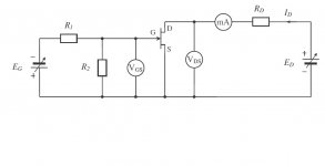
If you give me some more info on actual resistor values I can easily set up this test circuit and do some measuring
those resistor just have to reduce the current , so the power dispation would be within jfet limit
those resistor just have to reduce the current , so the power dispation would be within jfet limit
And both voltage source polarities reversed for P channel J74 I assume.
Is this schematic slightly wrong?
I set up for both N and P channels and was not getting any current flow.
When I removed the source voltage for the gate ie gate at source voltage through R2 then the Vds dropped and I got current flow.
Is it the polarity of Eg shown the wrong way round in the diagram (for N channel set up)?
I haven't tested this yet because my dual variable supply is +V 0V -V.
The resistor values I am using are;
R1 - 5k1
R2 - 560k
Rd - 2k
Attachments

Think I have found the problem, my supplies have a minimum output of 1.25V which is enough Vgs to 'switch off' the current flow.
Have slightly modified the circuit and at 10V Ed get around 5mA with 0Vgs, increasing Vgs reduces Ids and zeros around 0.6Vgs.
Hopefully can start taking some meaningful measurements now!
Have slightly modified the circuit and at 10V Ed get around 5mA with 0Vgs, increasing Vgs reduces Ids and zeros around 0.6Vgs.
Hopefully can start taking some meaningful measurements now!
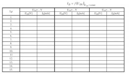
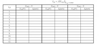
messure at Vd-10V and make the graph Vgs/ Id , compare with graph attached in the data sheet for J74 , it will confirm , your devices are origin Toshibas 🙂
messure at Vd-10V and make the graph Vgs/ Id , compare with graph attached in the data sheet for J74 , it will confirm , your devices are origin Toshibas 🙂
Have done that and looks good to me, just trying to get in a file/format/size that will be acceptable to upload, I really don't like computers sometimes!🤐
WOW - what a device😱Get a Peak DCA75 made in the UK.
No need for google and data sheets anymore.......
- Status
- Not open for further replies.