HI guys,
I'm building a front stage for a mosfet amplifier and i'm having trouble stabilizing it.
First i use POT 1 to set 4mA current through J3.
After that i use POT 2 to set the output DC offset to 0. It works ok till i'll approach 30mv at the OUT ( 0V IN). At that point the system oscillates at 2-3 MHZ at an amplitude of 30mV.
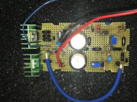
For the moment i use a test breadboard.
What i have already tried out:
any other ideas?
I'm building a front stage for a mosfet amplifier and i'm having trouble stabilizing it.
First i use POT 1 to set 4mA current through J3.
After that i use POT 2 to set the output DC offset to 0. It works ok till i'll approach 30mv at the OUT ( 0V IN). At that point the system oscillates at 2-3 MHZ at an amplitude of 30mV.
For the moment i use a test breadboard.
What i have already tried out:
- have shielded the feedback trace and the one that goes to M11's gate.
- have lower the gain to 4.7,
- put an 10nF capacitor over R15
- tried both differential and single input
any other ideas?
Attachments
Last edited:
I simulate it in Circuit Lab.simulate your design in ltspice, it might divulge what is going on.
It works perfectly!
thanks for suggestion!
Does it oscillate without the feedback? Sounds marginally unstable.
no, without feedback is ok.
thanks!
no, without feedback is ok.
thanks!
Ok, increase the hf gain by adding a series RC network across R10.
Try R=100R, and use C ~ 18nF. Does that kill the oscillation?
No compensation on the voltage amplification stage (top MOSFET), that could be a place to start.
You need gate protection networks BTW, power MOSFETs self-destruct instantly on gate-source over-voltage. A 15V zener across gate-source on each MOSFET should do the job.
Its not clear how you are powering the opamp.
You need gate protection networks BTW, power MOSFETs self-destruct instantly on gate-source over-voltage. A 15V zener across gate-source on each MOSFET should do the job.
Its not clear how you are powering the opamp.
Op amp is powered between ground and the negative rail, hopefully with some local decoupling.
I would try increasing R14 and R16 significantly, roughly 10k.
I would try increasing R14 and R16 significantly, roughly 10k.
Last edited:
At this stage it is a two stage amplifier to end up as three. You must have a stage which will carry the dominant pole . Generally, the VAS is assigned by adding a Miller capacitor from drain to gate . First the input differential 's pole needs to pushed as high as possible for high NFB . Reduce the feedback resistors by 10 fold . Apply a capacitor grounding the gate of J2 , that you can brave it to be HF filter . You can add a resistor on the collector of Q4 same vale as pott2 in order to apply a series RC between collectors .
Thank you all for your suggestions!
i'll try your suggestions tonight when i'll came back from work.
As rayma said, the OpAmp is power from ground to negative supply. A 1uF ceramic capacitor is used for local decoupling.
i'll try your suggestions tonight when i'll came back from work.
As rayma said, the OpAmp is power from ground to negative supply. A 1uF ceramic capacitor is used for local decoupling.
So the opamp might easily drive the lower FET gate up to the ground rail, zapping its gate oxide... Definitely need a zener to protect it. The upper FET too although pot2 affords some protection.
Today i had some time to work on the prototype again. And i started to try your suggestions from top to bottom.
So, first i checked again that the amp does not oscillate without feedback just to confirm what rayma asked me to check first time. To my surprise i found that it does oscillate ; it just that without feedback the offset voltage is around 55V DC, so the first time i checked i failed to see the other 30mV AC on top of it .
So the Op Amp went out the next second, and things get better immediately.
The offset still wonder 10 to 20 mV in either direction but i'm pretty sure this will stop when i'll connect it to earth or put it in a solid aluminium case.
i say this because the offset start wabelling if i move my hand above the board or in the immediate vicinity and it stops when i put one finger on the power supply ground).
thank you very much all!
i have attached the final scheme that tested ok.
Attachments
FYI, I had comparable issues during the design of my latest amp.
I remember, increasing VAS degeneration helped a lot in solving the stability issues.
I also did compare the 2sk216/2sj79 with the irf9610/710 combo. The irf sounded better, no matter what I changed regarding bias, degeneration...
Yesterday I had another audio lover visiting me, he really was impressed by the sound... Goosebumps
More info somewhere here:
https://www.diyaudio.com/forums/sol...low-nfb-fet-front-bjt-ops-13.html#post5916541
It does oscillate again if i remove C7.
I would still use a gate resistor on the lower mosfet.
one more remark:
It does oscillate again if i remove C7.
That's your phase-lead compensation. Without dominant pole compensation you're definitely going to need it. What are your phase and gain margins?
I agree with @rayma on a gate stopper for the CCS MOSFET.
Cheers,
Jeff.
BTW, if you want to improve your CCS without stability issues, use a second MOSFET rather than an opamp:
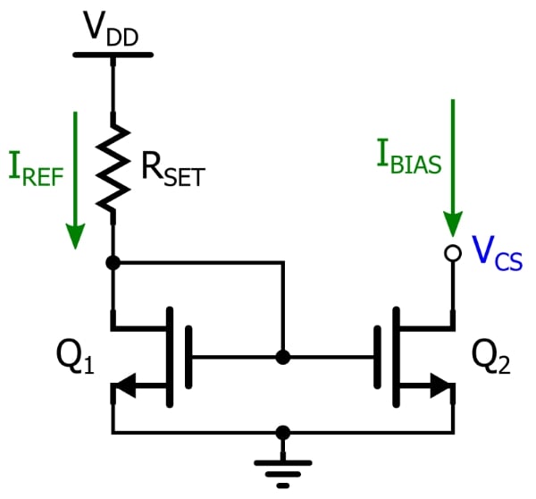
Yes, the suggested method of CCS as above is very stable with temperature changing. Note that Q1 & Q2 should be matched Vgs to reduce offset.
You can try adding Cc to M11. Phase lead compensation maybe is not enough in this case due IFN146 is a high gain Gm JFET. A combination of phase lead compensation and ordinary Miller compensation usually more stable.
Regards,
Cuong Nguyen
You can try adding Cc to M11. Phase lead compensation maybe is not enough in this case due IFN146 is a high gain Gm JFET. A combination of phase lead compensation and ordinary Miller compensation usually more stable.
Regards,
Cuong Nguyen
What is the dominant pole, M11? You may have to increase R14 in order to slow down M11.
Be sure that you do not have grounding problems that are not covered by simulation.
Be sure that you do not have grounding problems that are not covered by simulation.
- Home
- Amplifiers
- Solid State
- Front Stage oscillating problem