Re the buzz sound it could be you have established an earth point on a straight wire connection between the two supply capacitors where there are large charging currents passing. It would be as well to look at some threads dealing with earthing.
If so, for the meantime convert this junction into a T shape and establish your earth connections on the extended addition - taking these in order of from dirtiest being closest to the junction.
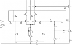
As far as your op.amp goes unless this is directly connected to the signal end of R45 you should use a resistor to buffer the output - this to eliminate the impacts due to whatever reactive elements there may be in the wiring connection.
I am assuming this is a separate line stage and not part of a compound arrangement combining the two circuits as one negative feedback unit.
It is not clear how you have implemented V13 possibly a zener diode (noisy) or a 7905 regulator. The internal working in latter include an op.amp - so attention has to be paid to decoupling a risk that in the circumstances you should avoid I think. A transistor or FET constant current regulator is another option.
If so, for the meantime convert this junction into a T shape and establish your earth connections on the extended addition - taking these in order of from dirtiest being closest to the junction.
As far as your op.amp goes unless this is directly connected to the signal end of R45 you should use a resistor to buffer the output - this to eliminate the impacts due to whatever reactive elements there may be in the wiring connection.
I am assuming this is a separate line stage and not part of a compound arrangement combining the two circuits as one negative feedback unit.
It is not clear how you have implemented V13 possibly a zener diode (noisy) or a 7905 regulator. The internal working in latter include an op.amp - so attention has to be paid to decoupling a risk that in the circumstances you should avoid I think. A transistor or FET constant current regulator is another option.
Re the buzz sound it could be you have established an earth point on a straight wire connection between the two supply capacitors where there are large charging currents passing.
You’re spot on with this. I also suspect that is power supply related. I use the same power supply for both channels, and sometimes when I touched the speaker connector of one speaker I could hear a small crack in the other speaker. the only thing common is the power supply…
The best thing: tonight when I came home the hiss is barely hearable and it also have no reaction when I touch the speaker connector with my hand. Self-healing by design
As far as your op.amp goes unless this is directly connected to the signal end of R45 you should use a resistor to buffer the output - this to eliminate the impacts due to whatever reactive elements there may be in the wiring connection.
OpAmp is history! I’m seduced by the way it sound already. No plan to complicate the design further. I’ll try to make a CCS with a Mosfet mirror just to see how it’s sounds, but if the sound will keep on improving as it happened in the last two days I might dump this idea too.
I am assuming this is a separate line stage and not part of a compound arrangement combining the two circuits as one negative feedback unit.
Yes indeed have two complete separate stages. The second one is more a power buffer than an output stage, since is totally separated. It’s a no feedback class A Mosfet with separate power supplies. I’ve built this power buffer 1 month ago and I have tried it with quite a few amps and preamps and by now I know it’s behaving and voice. These problems did not came from there.
It is not clear how you have implemented V13 possibly a Zener diode (noisy) or a 7905 regulator.
It’s a LM4040AIZ voltage reference. I had them around from a previous project. I was planning to use a precision reference like LT1021, but know I dumped this idea too. No need for something better.
Attachments
Last edited: