Think about the last time you had a complete hearing test, including a graph of the minimum low level sounds that can be heard, versus frequency?
Do not get discouraged if you do not like the graph, you have to remember the Fletcher-Munson effect.
Our ability to hear extremely low amplitude mid frequencies is far better, than to hear extreme low frequencies and extreme high frequencies.
Do not get discouraged if you do not like the graph, you have to remember the Fletcher-Munson effect.
Our ability to hear extremely low amplitude mid frequencies is far better, than to hear extreme low frequencies and extreme high frequencies.
The OP asked to share the simulation file from #22 post.
This is "general" schematic, the interstage and the OPT is the "sample".
To use it must to download Stephie Bench dropdown tube menus:
Drop Down Menus for selecting your tube - Intact Audio
This is "general" schematic, the interstage and the OPT is the "sample".
To use it must to download Stephie Bench dropdown tube menus:
Drop Down Menus for selecting your tube - Intact Audio
Attachments
also I notice you use a 470R as a grid stopper, I assume there are two of these running separately? Mine has two 1K grid stoppers and I was thinking of swapping to 500R as I have some Shinkoh 2W at that value and I like the sound of the Shinkoh 2W 500R in my preamp as grid stoppers there.
Thanks again
Thanks again
This sample use "real" (measured) transformers, 1:1 IT and 14k:8 OPT.
The 211 operating point is the same as OP's amplifier (sent me pics from inside of the amp).
p.s. to Rich:
The RIFA 100uF 100V (211 cathode decoupling) is tied tightly to cathode resistor, where the dissipation is 2.5W.
Sooner or later the capacitor will be dry out and amplifier behaviour will be degrading.
The are another (unused snap in) capacitor, I think it was the original cathode decoupling capacitor. If it good, use it instead of RIFA.
Attachments
6C45P has two grid pins (2, 8).
MUST to use on both pins grid stoppers!
Carbon comp resistors (as in your amp Allen Bradley ones) is the best here.
Commonly power tubes don't require grid stoppers.
MUST to use on both pins grid stoppers!
Carbon comp resistors (as in your amp Allen Bradley ones) is the best here.
Commonly power tubes don't require grid stoppers.
p.s. to Rich:
The RIFA 100uF 100V (211 cathode decoupling) is tied tightly to cathode resistor, where the dissipation is 2.5W.
Sooner or later the capacitor will be dry out and amplifier behaviour will be degrading.
Are there any sound quality choices to be made with this capacitor.
I think the unused capacitor is only to cover a hole in the amplifier top plate that was originally designed to have 2 valves as I was in first instance thinking of following the Ongaku circuit.
I can use this location for sure
The worst thing that can happen to tube, using cathode decoupling. 😛
The decoupling capacitor quality is immediately audible.
I neglect it (if possible), but if I have to use it, I search the most better capacitor as available: Black Gate, Elna Cerafine, or now when these are rare, AN Kasei.
The decoupling capacitor quality is immediately audible.
I neglect it (if possible), but if I have to use it, I search the most better capacitor as available: Black Gate, Elna Cerafine, or now when these are rare, AN Kasei.
ok - will hunt out something magical!!
I actually quite like Elna Silmic as an affordable option in other locations
🙂
I actually quite like Elna Silmic as an affordable option in other locations
🙂
Are there any calculators suitable for the 211 valve to understand the capacitor value that is appropriate - I can find plenty of the more familiar valves?
I can assume I suppose that original designer got the 100 uF right, but it would be interesting to check
Thanks for all the help 🙂
I can assume I suppose that original designer got the 100 uF right, but it would be interesting to check
Thanks for all the help 🙂
That's really great thanks.
I found this too Cathode Bypass Capacitor Calulator
I measured my cathode resistor Rk and it is 1K
I found this too Cathode Bypass Capacitor Calulator
I measured my cathode resistor Rk and it is 1K
Attachments
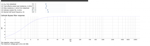
It shows that 100uF is enough.
Examine the unused snap in capacitor, if it's lower than 100uF (for example 47uF), try it.
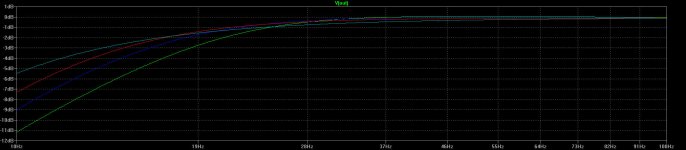
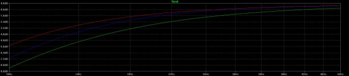
Use REW from 10Hz, not 15Hz for better visible separation.
p.s.
Your amp probably the DIY building, using TRON modules, based on early prototype.
See the recent TRON 211 amp: Telstar - Tron Electric
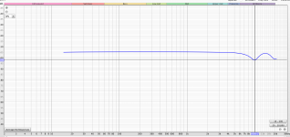
TRON quality is enough good to suppose, that own parts don't generate such frequency anomalies at 10kHz, so probably the output parts (211, cathode block, OPT) responsible for this.
Examine the unused snap in capacitor, if it's lower than 100uF (for example 47uF), try it.
Use REW from 10Hz, not 15Hz for better visible separation.
p.s.
Your amp probably the DIY building, using TRON modules, based on early prototype.
See the recent TRON 211 amp: Telstar - Tron Electric
TRON quality is enough good to suppose, that own parts don't generate such frequency anomalies at 10kHz, so probably the output parts (211, cathode block, OPT) responsible for this.
The amp was built by Graham who is the guy behind Tron and does all the design work. I started to build and design a 211 based upon the Onkagu circuit and then ran out of talent..... My brother took it to Graham and he was able to build this amplifier based upon his Telstar. At the time the larger transformers were not very commercial due to size and weight; once complete we preferred the sound of this to his Telstar of the time. It was build around 20 years ago I think.
The unused capacitor is 160 uF.
The unused capacitor is 160 uF.
As the loudspeaker (crossover) can altering 10kHz "valley" to 12kHz - IMHO with OPT "under fitting"- makes it probable, that OPT would be the problem cause.
By all means try another cathode decoupling capacitor (to rule out it's liability).
For the measuring the "quality" is unimportant, if it's good (low ESR) for few ten kHz.
By all means try another cathode decoupling capacitor (to rule out it's liability).
For the measuring the "quality" is unimportant, if it's good (low ESR) for few ten kHz.
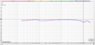
Output transformer frequency response:
The 4 Ohm tap will almost certainly have higher leakage reactance than the 8 Ohm tap.
But the 8 Ohm load is larger than a 4 Ohm load, relative to the higher leakage reactance of the 4 Ohm tap.
And so the high frequency response due to the leakage reactance, and its combination with the distributed capacitances can not be easily predicted . . .
So . . .
First measure with a resistive 8 Ohm load on the 4 Ohm tap.
Second, see what your amplifier frequency response of the 4 Ohm tap is into your "8" Ohm loudspeaker:
For the loudspeaker as test load, use the "Denon Technical Audio CD". It has a repetitive pulse, the pulse is only 1 sample wide (1/44.1kHz = 22.7usec wide).
That narrow impulse and low repetition rate will allow you to apply it from your amplifier to the speaker, and not burn out the tweeter.
You will need a digital scope that has an FFT function to easily and quickly see the frequency response.
Then repeat the impulse test, but with the resistive 8 Ohm load, and compare.
Last edited:
- Home
- Amplifiers
- Tubes / Valves
- Frequency Roll off changed - ideas