The only other place I can see might produce a rolloff is the first bypass cap (C1). If its not good at HF then the gain will drop. I would be surprised.
The 6C45P cathode bypass capacitor is indifferent for HF behaviour.
If use the amp without it, practically only the gain and LF behaviour changing.
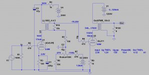
The IT coupled 6C45P, fix biased 211 SE is as simple as possible.
No capacitor in the signal path (except last PSU capacitors and first stage cathode bypass), VAS stage->interstage->grid of 211->OPT.
The cause of HF rolloff mostly due to the interstage, the OPT, and depends less on other devices in amplifier (if tubes are working properly).
As I wrote earlier the unsatisfactory OPT loading (mostly due to winding ratio and loudspeaker impedance curve) can cause some anomalies.
This, with OPT own HF rolloff, may results deeper rolloff as expected.
If use the amp without it, practically only the gain and LF behaviour changing.
The IT coupled 6C45P, fix biased 211 SE is as simple as possible.
No capacitor in the signal path (except last PSU capacitors and first stage cathode bypass), VAS stage->interstage->grid of 211->OPT.
The cause of HF rolloff mostly due to the interstage, the OPT, and depends less on other devices in amplifier (if tubes are working properly).
As I wrote earlier the unsatisfactory OPT loading (mostly due to winding ratio and loudspeaker impedance curve) can cause some anomalies.
This, with OPT own HF rolloff, may results deeper rolloff as expected.
Attachments
Then again, it would be good to know if the amp was having this issue from day one or did it show later.
Last edited:
Get a meter with a good AC frequency response. Even an old Fluke 8050 is good for audio work. You'll have much better accuracy than an oscilloscope. I fixed up an old Keithley 195 bench meter and it's more than paid for itself.
Any modern oscilloscope, digital or analog, that can not properly measure the very large amount of rolloff that is shown in Plot # 14, I would throw in the trash.
DC to above Audio frequencies is not a problem.
But, those who use a scope probe, and forget to compensate it on a square wave . . .
Well, that is cause for large measurement errors.
Nuf Said
DC to above Audio frequencies is not a problem.
But, those who use a scope probe, and forget to compensate it on a square wave . . .
Well, that is cause for large measurement errors.
Nuf Said
Last edited:
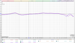
So I have now used REW to drive the input and measure the output on the 211 amp. First tests below, the difference is L and R channels.
I left the speaker in circuit playing while taking a tap off the terminals on the amp to drive the phono input on the audio interface.
Thoughts?
I will in due course swap valves and see how this affects anything on L and R balance.
I left the speaker in circuit playing while taking a tap off the terminals on the amp to drive the phono input on the audio interface.
Thoughts?
I will in due course swap valves and see how this affects anything on L and R balance.
Attachments
"I left the speaker in circuit"
The diagrams shows the speaker (and crossover, if it contains it) impedance fluctuations rather than amplifier behaviour.
If you want correct measuring, must to use real ohmic (8R or 4R 50..100W) load.
The diagrams shows the speaker (and crossover, if it contains it) impedance fluctuations rather than amplifier behaviour.
If you want correct measuring, must to use real ohmic (8R or 4R 50..100W) load.
Actually, it is a real good idea to make both tests.
Test with a resistor load.
Test with a loudspeaker load (be careful to do this with very low power, and also earplugs). You do not want to burn out the tweeter, and you do not want to burn out your ears.
Compare.
You can see the effect of the loudspeaker's impedance versus frequency, as it presents a real-world load to the amplifier.
I use my scope FFT, and a Denon Audio Technical Test CD.
It has a single impulse, and repeats at a low repetition rate, so the power to the loudspeaker is low (and the frequency is spread across the audio range all the way to 22.05kHz.
Last edited:
Actually, it is a real good idea to make both tests.
Test with a resistor load.
Test with a loudspeaker load (be careful to do this with very low power, and also earplugs). You do not want to burn out the tweeter, and you do not want to burn out your ears.
Compare.
You can see the effect of the loudspeaker's impedance versus frequency, as it presents a real-world load to the amplifier.
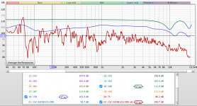
Well so here is an interesting combination which seems to show a consistent (in many ways) frequency characteristic in the amplifier.
Thoughts welcome
The traces are as follows:
Green test sweep into 211 amp driving 8 ohm resistor - measured output of amp
Blue test sweep into 211 amp driving Klipsch Heresy speaker - measured output of amp
Red test sweep into preamp, driving 211 amp, driving Klipsch speakers - measured output with microphone in room.
Attachments
1.) Be sure that amplifier's input sweep is "horizontal" -at least- from 10Hz to 20kHz: measure it with the same method.
2.) If it's good, -as I wrote earlier- the interstage -and mostly- the OPT produces such anomalies.
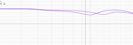
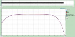
I attach one of my friend's 211 amp frequency curve (I measured in last week) as "benchmark":
-3dB 19Hz..30kHz -at 1W- is acceptably good for 211 amps.
2.) If it's good, -as I wrote earlier- the interstage -and mostly- the OPT produces such anomalies.
I attach one of my friend's 211 amp frequency curve (I measured in last week) as "benchmark":
-3dB 19Hz..30kHz -at 1W- is acceptably good for 211 amps.
Attachments
I think there may be something wrong with the amp given you're seeing 8dB drop at 10kHz with a resistive load. Without a schematic of the amp it's going to be hard to say if this is inherent to the amplifier's design, or if a component has failed.
The impedance of the Klipsch is certainly not 'tube amp friendly' but I think there is more at play here than just that.
The impedance of the Klipsch is certainly not 'tube amp friendly' but I think there is more at play here than just that.
Did you calibrate your AI first? You do this by putting the OP straight into the IP,then run a frequency response. I've had some odd anomalies with REW sometimes. Sometimes it's easier and more reliable to just use a sig gen and a scope and do a manual sweep. Most analogue sig gens have a x10, x100 & x1000 etc setting,for a quick test all you need to do is flick from one range to another.
Might be worth doing the above to verify your finding with REW.
Andy.
Might be worth doing the above to verify your finding with REW.
Andy.
If the OP turn off the amplifier (remove power cable!) for at least half hour, then pull out tubes and shorted last PSU capacitor (practically shorting bleeder resistor), possible to measure only the OPT.
Signal generator (or DAC output) -> appropriate series resistor -naming Rx- (signal source output impedance + Rx = 3300R ) -> 211 socket anode pin -> OPT -> 8R load -> REW measurement input.
The measurement is the same as with working amplifier. The requiring voltage is 1-4V on anode pin.
Signal generator (or DAC output) -> appropriate series resistor -naming Rx- (signal source output impedance + Rx = 3300R ) -> 211 socket anode pin -> OPT -> 8R load -> REW measurement input.
The measurement is the same as with working amplifier. The requiring voltage is 1-4V on anode pin.
The traces are as follows:
Green test sweep into 211 amp driving 8 ohm resistor - measured output of amp
Blue test sweep into 211 amp driving Klipsch Heresy speaker - measured output of amp
Red test sweep into preamp, driving 211 amp, driving Klipsch speakers - measured output with microphone in room.
These are all very as much normally expected. The first high frequency resonance at 10KHz is disappointing, but it costs considerable money to get the next octave through a high impedance output transformer. There are very good reasons why type 211 valves aren't used everywhere, and you've just documented the biggest hurdle. Wonderful linearity, but expert-level everything else needed.
In-home microphone measurements are meaningless without detailed description of the mic distance, axis, yada yada, and are even then only vaguely translatable to other spaces. Doesn't matter.
Good news: nothing looks broken.
All good fortune,
Chris
Last edited:
These are all very as much normally expected. The first high frequency resonance at 10KHz is disappointing, but it costs considerable money to get the next octave through a high impedance output transformer. There are very good reasons why type 211 valves aren't used everywhere, and you've just documented the biggest hurdle. Wonderful linearity, but expert-level everything else needed.
In-home microphone measurements are meaningless without detailed description of the mic distance, axis, yada yada, and are even then only vaguely translatable to other spaces. Doesn't matter.
Good news: nothing looks broken.
All good fortune,
Chris
I know the circuit is in simple schematic terms
6c45Pi
Lundahl 1660 interstage
211
output transformer
Can I assume the 10 Khz resonance is the amplifier as it was built rather than a failed component. I will in due course also test the RH channel, and also calibrate the REW with the audio interface.
to be honest it sounds pretty good,
You have two pretty high impedance transformers, and really need to expect that a 1000:1 frequency range is pushing expectations. Not the end of the world, even really good speakers don't really do a whole lot better, or as well. But nothing is broken - high impedance wide-bandwidth transformers are difficult to impossible, depending on your interpretation.
All good fortune,
Chris
All good fortune,
Chris
I am going to try the 4 ohm tap with the Klipsch speakers soon, this might change things - maybe for the better do you think?
I'd bet that it already sounds great. Please, enjoy playing with it as a toy, but don't let that interfere with your enjoyment of music. Audiophiles are a sad shambling lot needing professional intervention. Beware the zombie audiophilecalipse.
Always the best,
Chris
Always the best,
Chris
I'd bet that it already sounds great. Please, enjoy playing with it as a toy, but don't let that interfere with your enjoyment of music. Audiophiles are a sad shambling lot needing professional intervention. Beware the zombie audiophilecalipse.
Always the best,
Chris
great advice // actually some of the best sounds I've ever had at the moment so why try to fix a problem that is not really significant. Just a slight loss of 'presence' at low volumes. BUT very natural and organic without HIFI 'detail' but loads of resolution so maybe better the devil I know
- Home
- Amplifiers
- Tubes / Valves
- Frequency Roll off changed - ideas