Thanks Dave, now I know what the ripple sound is. I do remember the Frugal and the A126 were smoother and had abit more finesse to their sound over the cabs I built.
I should get that tube back to you or get you some coinage for it soon too. I've been quite sold on a 5965 nos RCA in my amp and will most likely just leave it like that and have hardly used the Tele or any 12ax7 since I tried the 5965. Dave🙂
I should get that tube back to you or get you some coinage for it soon too. I've been quite sold on a 5965 nos RCA in my amp and will most likely just leave it like that and have hardly used the Tele or any 12ax7 since I tried the 5965. Dave🙂
DaveCan said:I should get that tube back to you or get you some coinage for it soon too
Just send money 🙂
dave
planet10 said:[B
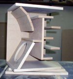
And speaking of BIBs... i just finished a set of drawings for my twist on an FE126/FE127 BIB.
[/B]
Dave, your twist looks great! Much more practical (to me) than the traditional BiB enclosure.
Do you have a modelled FR for the enclosure?
GG said:Do you have a modelled FR for the enclosure?
It is the standard FE126/127 63 in^2 BIB, inverted with the addition of the K-Slot... oh and the driver moved to more optimal position. Scott could generate a FR of it without the slot. I think i heard that MJK may be considering the k-slot. The hope here is that it reduces the Q of the resonance and smooths out the ripple a bit.
dave
Dave Cigna said:The idea excites me. The slot(s) serve to de-Q the resonances. Hopefully it affects the higher harmonics more than the fundamental 1/4 wave mode, which we want to keep. Haven't come to a conclusion about that. And then the improved Zd...
The whole thing would need to be longer than MJK's worksheets suggest; they don't include this sort of variation, so we're back in the dark - or at least the light isn't quite as bright.
Driver height is just about right with the 126/127...
-- Dave
p.s. Those feet are lovely. I wanted to mention that. 😎
I am following this thread with great interest. I like the idea of inverting the BIB as this would help with the bass reponse while still being able to use a reasonably small (short) cabinet. Does anyone have the formulas for the K slots? Dave the idea of putting the slots on the side is brilliant. this makes the build easier and keeps the cost down. I don't presume to understand the math behind the design but I would sure like to hear the speaker when the dust settles.
G said:Does anyone have the formulas for the K slots? Dave the idea of putting the slots on the side is brilliant. this makes the build easier and keeps the cost down. I don't presume to understand the math behind the design but I would sure like to hear the speaker when the dust settles.
Excel calculator --> http://members.aol.com/klehma/karlson.html?mtbrand=AOL_US
An externally hosted image should be here but it was not working when we last tested it.
http://home.planet.nl/~ulfman/
dave
I might offer a word of warning to anyone thinking of cutting a k slot into a horn cabinet.
It might not be the case for every design, but I tried this on the dalek's, by cutting a diamond shaped hole in the back panels, calculated to open in conjunction with the original angled mouths, so that the opening began at 7/8 length. The result was less than satisfactory, so I glued the pieces back in again. I was indeed trying to flatten LF response (which it certainly helped), but the muddy blurred sound that resulted was worse than the uneven response. The whole attraction of the horn's impact instantaneously vanished.
Don't get hung up on flat response, as trying to achieve it could ruin a nice sounding speaker.
I am now thinking that after that experiment that a very sharp termination is best (at least for my tastes).
planet10 said:
Excel calculator --> http://members.aol.com/klehma/karlson.html?mtbrand=AOL_US
An externally hosted image should be here but it was not working when we last tested it.
http://home.planet.nl/~ulfman/
dave
Thanks Dave but I don't know enough to apply the calculations to the BIB. Not enough knowledge of the fundamentals. Does it matter that the Kslot will not be directly in front of the driver as it would in a normal Karlson cab?
well you can see the design at...
take a look in the gallery at the full range driver site.
http://fullrangedriver.com/gallery/
take a look in the gallery at the full range driver site.
http://fullrangedriver.com/gallery/
PS...
The first version of these ran FE167E's and the current versions run FE166E's. There is only 1/4 inch wool felt linning the rear line. The current versions also have different tapers on the coupler section. They will not make bass like a BIB but they can be run full range depending upon your taste in music. They do benefit from the addition of a good set of subs.
The first version of these ran FE167E's and the current versions run FE166E's. There is only 1/4 inch wool felt linning the rear line. The current versions also have different tapers on the coupler section. They will not make bass like a BIB but they can be run full range depending upon your taste in music. They do benefit from the addition of a good set of subs.
Moray,
I assembled the 4 pdfs & the picture into a single pdf (and will probably do a sketchUp 3D of it (i need the practise) ... can i post it in the box library?
dave
I assembled the 4 pdfs & the picture into a single pdf (and will probably do a sketchUp 3D of it (i need the practise) ... can i post it in the box library?
dave
That is very kind of you...
thank you Dave, I would consider it an honor to be published in such fine company. Send me a PM and I can tell you what the new tapers are like. If I can figure out how to do it I will attempt to scan a drawing with some dimensions and send it to you. Best regards Moray James.
thank you Dave, I would consider it an honor to be published in such fine company. Send me a PM and I can tell you what the new tapers are like. If I can figure out how to do it I will attempt to scan a drawing with some dimensions and send it to you. Best regards Moray James.
Dave,
I'd really like to see your sketchup of the iBIBk. I just don't understand the Karlson slot and can't get my minds eye around the 2D drawings. It would be interesting to fly around them if you posted them to the 3D-Warehouse site, though I don't know how to look at interior parts or make exterior parts transparent.
I'd really like to see your sketchup of the iBIBk. I just don't understand the Karlson slot and can't get my minds eye around the 2D drawings. It would be interesting to fly around them if you posted them to the 3D-Warehouse site, though I don't know how to look at interior parts or make exterior parts transparent.
mrpopgun said:I'd really like to see your sketchup of the iBIBk.
I'd actually have to do a 3D 1st. Easier to start from scratch than fix what i have done already thou.
dave
Mr. Popgun,
The bottom is open on the iBIBk, but that terminus is quite close to the floor compared to other floor terminus BIB's, so Dave added the K-slot shaped opening at the bottom of the rear panel.
I do notice some vibration near bottom, so I am going to add a cross brace at the bottom rear because that corner is unsupported. I'll also play around with different lift heights to see what difference that makes, since the bottom is open.
Thanks for the feedback on the K-Slot. Indeed, it would be hard to fly around if it hasn't yet been 3D'd 🙂
Looking at the plans, on the side profile there is the red rectangle rising from behind the closed end of the baffle on up and is labelled "cut-Out from Karlson Slot". I don't understand this. Tracing over to the head on view, I don't see a corresponding line to indicate if this is a piece tacked on to the backside of the baffle nor corresponding lines in the wall material to make me think it is a slot cut into the side of the walls of the speaker. Also, it doesn't seem to be cut-out of the baffle itself or out of the back wall of the cabinent. I just don't know how to read this.
Thanks,
Pop
mrpopgun said:Thanks for the feedback on the K-Slot. Indeed, it would be hard to fly around if it hasn't yet been 3D'd 🙂
Looking at the plans, on the side profile there is the red rectangle rising from behind the closed end of the baffle on up and is labelled "cut-Out from Karlson Slot". I don't understand this. Tracing over to the head on view, I don't see a corresponding line to indicate if this is a piece tacked on to the backside of the baffle nor corresponding lines in the wall material to make me think it is a slot cut into the side of the walls of the speaker. Also, it doesn't seem to be cut-out of the baffle itself or out of the back wall of the cabinent. I just don't know how to read this.
Thanks,
Pop
Pop,
That's Dave recycling the piece cut out from the K-slot. It also maintains the overall terminus CSA, although I can't really imagine it having any audible impact. Mine sound fine without it.
johninCR said:That's Dave recycling the piece cut out from the K-slot. It also maintains the overall terminus CSA, although I can't really imagine it having any audible impact. Mine sound fine without it.
It's primary purpose is to give enuff wall depth to mount the specific feet i have,
The k-Slot + the openings at the bottom on the sides & front are equal to the mouth area.
3D model (sans the k-slot piece that was confusing mtpopgun) are up in the 3D warehouse titled "iBIBk". I also just substitued cylinders intead of modeling my feet.
dave
Edit: Note: there is an extraneous line in the 3D (at the bottom of the k-slot) that should be deleted.
Attachments
The Sketchup is terrific and very much illuminates what I needed to see. These inverted designes interest me, even apart from the K-Slot. Rooms with tall ceilings, or homes with little tykes who are budding basketball stars could benefit from the bottom vs top opening.
In comparing the inverted to the non-inverted, what sort of difference does the gap between the mouth and loading surface (floor or ceiling) make in the resultant sound? Does more gap (ie upright) result in a but more airy, open sound? Does less gap (ie inverted) make for a more controllable sound due to being able to tune the overall cabinent height off the floor? How does the surface of the loading plane effect the sound ie plastered ceiling vs carpeted floor?
Hmm, you know, I've got the wood, guess I'm just going to have to knock something up, though it will be a double speaker jobber since all I have are 16-ohm speakers. Any recommendations on adhesive with enough hold to keep these heavy things together while moving them into the house while being temporary enough to be able to break the boxes back down in order to use the wood in other ways?
- Status
- Not open for further replies.
- Home
- Loudspeakers
- Full Range
- Fostex 126e or 127e