The fact that it produces the top/bottom of the waveform perfectly when only one output is in the circuit is very strange. I would expect one to produce very distorted output if it draws excessive current with the bias transistor shorted. Are you sure that there are no drops of solder or other solder bridges on the board in this channel?
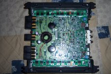
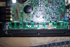
Looks like a 200.4 not a 200a4. Rockford used BUZ 21 and BUZ 272 for output transistors in the 200.4 and IRF540 and IRF9540 in the 200a4. I see in the last pic a transistor with clipped leads. Probably was shorted and blowing the fuse. Assuming they clipped it to get the amp to power on again. One side of the amp probably still works and the other side has no sound or static??? What test have you performed???
If it works perfectly sometimes and other times it won't power up, I'd suspect that the remote turn-on terminal has bad solder connections.
I'm assuming that you've confirmed that the power/ground and remote connections/supplies are all OK.
I'm assuming that you've confirmed that the power/ground and remote connections/supplies are all OK.
When driven into hard clipping with only the 540 installed the output will distort badly. But with only 9540 in the output will flatten out like normal as it does all of the other channels. This is with using the outputs from the other channel, bias pot all the way down and the bias in transistor shorted.
Looks like a 200.4 not a 200a4. Rockford used BUZ 21 and BUZ 272 for output transistors in the 200.4 and IRF540 and IRF9540 in the 200a4. I see in the last pic a transistor with clipped leads. Probably was shorted and blowing the fuse. Assuming they clipped it to get the amp to power on again. One side of the amp probably still works and the other side has no sound or static??? What test have you performed???
IRF540 & IRF9540 are good direct replacements right? Just in case if its in the output stage that is shorted.
i just pulled this amp back out and still can't figure it out. today i powered it up directly with a 10a fuse and the amp would come on and pull about 5-6 amps. with all the parts in the amp the outputs in that 1 channel would still get hot and after a few seconds the cap in the zobel network got very hot. i removed it and it tested faulty, so i left it out and the amp now pulls about 2-3 amps of current. i know that if i pull either 1 of the drivers or either 1 of the fets all current draw goes away and everything runs cool.
PC-3084?
The schematic Diagram has that as the RR channel.
Lift Q405 and Q406 and reinstall the other transistors that you removed. Does it still draw excessive current?
I'm assuming that you've set the bias pot fully counter-clockwise.
The schematic Diagram has that as the RR channel.
Lift Q405 and Q406 and reinstall the other transistors that you removed. Does it still draw excessive current?
I'm assuming that you've set the bias pot fully counter-clockwise.
PC-3084A
yes, bias fully counter-clockwise
i pulled Q405 and Q406 and it seems to do better
i don't have the zobel network cap in place, i'll have to order some. it's a .1uf smd cap and when i check it with my fluke 112 out of the circuit on capacitance check it reads about 50 nf
yes, bias fully counter-clockwise
i pulled Q405 and Q406 and it seems to do better
i don't have the zobel network cap in place, i'll have to order some. it's a .1uf smd cap and when i check it with my fluke 112 out of the circuit on capacitance check it reads about 50 nf
Q405 & Q406 check out ok.
R452 & R439 also check out ok. 1 is @ 554 & the other is @ 562 (both still in the circuit)
R452 & R439 also check out ok. 1 is @ 554 & the other is @ 562 (both still in the circuit)
Instead of jumping the bias transistor from collector to emitter, try connecting a jumper between the bases of the MPSA06 and MPSA56 driver transistors. Reinstall Q405 and Q406. Does it still draw excessive current?
i just got around to finishing my "switching box" and figured i would try it out.
it's been so long that i don't even remember the original problem for this one i just know it's been stacked up with a few others that i have previously given up hope on. i lucked out and and actually successfully repaired one of the other hopeless amps so now here i am...
with all parts installed in the amp i can get the output signal almost perfect in the defective channel and perfect in the other 3 channels. but i noticed that when i switch the x-over from lp-full-hp, lp is perfect, full is fuzzy and hp is very distorted. all 4 channels will act the same way. i haven't put a load on it yet. what could cause this?
Some of these amps had a lot of high frequency noise on the output but it was not audible.
Sometimes it helped if you used all 4 inputs or at least connected the front and rear input shields with a jumper.
Sometimes it helped if you used all 4 inputs or at least connected the front and rear input shields with a jumper.
i flipped the rca 2-4 switch so that 1 set of rca's provides audio for all 4 channels. it seems ok when i have my scope grounded to the shield ground but when disconnect my scope the output is distorted. is this just because of my setup or maybe is something open between shield and chassis ground?
- Status
- Not open for further replies.
- Home
- General Interest
- Car Audio
- fosgate x200.4