when i apply remote voltage the amp will constantly turn on and off (drawing current) i'm assuming that's the protection making it turn on and off. so i opened it a noticed the 2 filter caps (C26,C27) were bubbled out, i don't think they actually vented but i replaced them anyway. the amp still did the same thing (on/off) so i checked the rectifiers and found one bad (D9)(not shorted but the resistance check was out of tollerance). while i had the rectifiers out i powered up the amp with no problem (perfect square wave & virtually no current draw). so i replaced the bad one and reinstalleed the good one. but when i attempted to power up the amp it did the exact same thing (on/off). non of the outputs are shorted but i did notice that the Q410 & Q411 outputs were getting hotter than any of the other outputs. i removed them from the circuit and they checked out okay. while they were out i attempted to power up the amp with the same results (on/off). so i reinstalled them and removed their drivers (Q408 & Q409), they checked out okay. so i tried to power up the amp with them out and now the amp will stay on but is still drawing current.
I'm not sure where i should look next.
I'm not sure where i should look next.
Attachments
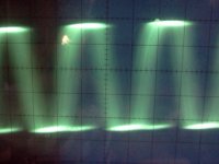
with the drivers (Q408 & Q409) still out i turned all 4 bias pots all the way down and all the exessive current draw went away. so i reinstalled the drivers and powered up the amp now it will stay on but is still drawing current and the same outputs will get hot. so i looked at the output of the defective channel and it has a fuzzy signal, i couldn't really get it locked in to my scope or i would give you a pic. the adjacent channel has a very small signal on it but i think it's comming from this channel. the other 2 channels seem fine.
When you checked the outputs, did you confirm that there was absolutely no continuity (OL on ohms) between the gate and the other two legs?
When the drivers were out, was there any DC voltage on the defective channel (measured directly across the speaker terminals)?
When the drivers were out, was there any DC voltage on the defective channel (measured directly across the speaker terminals)?
i just rechecked the outputs and they seem okay. i have some 540/9540's on hand, should i try those in place of the originals?
If there was infinite resistance between leg 1 and the other two legs, they're probably OK.
In some of these amps, Rockford used BUZxxx transistors that commonly failed shorted leg 1 to leg 3. This generally caused the half of the signal to be clipped but didn't cause excessive current draw.
When the drivers were out, was there any DC voltage on the defective channel (measured directly across the speaker terminals)?
If you short the collector and emitter of the bias transistor, does the current draw decrease?
With all components in the circuit.
With all components in the circuit.
Looking for one. I have a cheap walmart meter and wamt to upgrade. I don't see many of the 110-112.
I've never found a better meter than the 10, 11 or 12 for general troubleshooting. I have lots of other meters and most have more features but I rarely have anything other than a 10, 11 or 12 on the bench. Ebay has them fairly often. Expect to pay $35-$60 for them.
If you need a true RMS meter (rarely a necessity), you can buy a second meter. The 115 would be a good 'second' meter.
If you need a true RMS meter (rarely a necessity), you can buy a second meter. The 115 would be a good 'second' meter.
How do you check the driver transistors for a Rockford Fosgate Punch 75.2? I replaced a pair of output fets on one channel and it was working great for about 5 minutes or so then it blew out! But I think it blew because there may have been a soldered bridge I didn't check my work after I reassembled it. I thought I blew the powersupply because it made a nasty cooking cooking sound but the P-channel fet fried the board a little.
Were the transistors that you replaced how when they failed?
The driver transistors are bipolar transistors. If you're unsure how to test them, read the basic transistor testing page (link in sig line below). If you're still unsure, use the applet and post a screen cap of the readings.
The driver transistors are bipolar transistors. If you're unsure how to test them, read the basic transistor testing page (link in sig line below). If you're still unsure, use the applet and post a screen cap of the readings.
To be honest i am unsure how they failed but i did notice that, that side got kinda hot and the good side stayed cool. I was looking over the soldering i did and i don't think it had anything to do with it?? I had a spare pair of IRF540 and IRF9540 from harris like originals. I know how to test them but unsure if i have to check them with the amp on?
- Status
- Not open for further replies.
- Home
- General Interest
- Car Audio
- fosgate x200.4