That is very kind of you but NOT what I wanted !!
Why can you not tell me the manufacturer and part number? Is this only available in China?
I need to make up my own cables (screened).
Cliff
Why can you not tell me the manufacturer and part number? Is this only available in China?
I need to make up my own cables (screened).
Cliff
cliffforrest said:That is very kind of you but NOT what I wanted !!
Why can you not tell me the manufacturer and part number? Is this only available in China?
I need to make up my own cables (screened).
Cliff
Hi Cliff, this female connector is very common in China. Most of the 2.54mm female connectors will match the male connector in the main board
 Just like the two cable which connect the encoder and the controller board
Attachments

LU - I give up!
The reason I have been asking for days is that I cannot find a matching connector in Farnell, RS or any other European catalog or website.
All the ones with 0.1" pitch have 1mm pins, too big for the PCB!
bawling:
How is anyone else managing? Soldering direct t the PCB? I will not do this!
Cliff
The reason I have been asking for days is that I cannot find a matching connector in Farnell, RS or any other European catalog or website.
All the ones with 0.1" pitch have 1mm pins, too big for the PCB!
bawling:
How is anyone else managing? Soldering direct t the PCB? I will not do this!
Cliff
cliffforrest said:LU - I give up!
The reason I have been asking for days is that I cannot find a matching connector in Farnell, RS or any other European catalog or website.
All the ones with 0.1" pitch have 1mm pins, too big for the PCB!
bawling:
How is anyone else managing? Soldering direct t the PCB? I will not do this!
Cliff
soldering direct to the pcb is the better way.and that is easy.
Has anyone built their kit? How does it sound compared to whatever (please specify) what you were using before?
Interested in this set.... but not if its no better than the switches I already have here.
Fran
Interested in this set.... but not if its no better than the switches I already have here.
Fran
woodturner-fran said:Has anyone built their kit? How does it sound compared to whatever (please specify) what you were using before?
Interested in this set.... but not if its no better than the switches I already have here.
Fran
Hi Fran,
Do you need a Manual for preview? 🙂
regards
Lu
Problem with C5 ?
Hi
I tested my kit for the first time this evening.
Everything worked great and I even had my own choice of phono as source. thanks Lu 🙂 I havent tried any audio trough it yet though.
I was satisfied for the moment but exactly when I turned the power off, C5 on the mother board exploded . I havent changed it yet and I really hope that something else didn't got damaged.
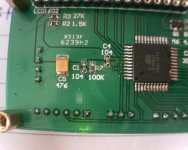
C5 is a small Elyth with a value of 470 stamped (47 uF ?) paralell to the incoming 5Volt. There is a short because my bench PSU goes into current limit.
I'll try some other lyth tomorrow.
Anyhow is the C5 of bad quality, to little voltage or was it turned backwards maybe? I don't know yet. Just want to tell you all.
Hi
I tested my kit for the first time this evening.
Everything worked great and I even had my own choice of phono as source. thanks Lu 🙂 I havent tried any audio trough it yet though.
I was satisfied for the moment but exactly when I turned the power off, C5 on the mother board exploded
. I havent changed it yet and I really hope that something else didn't got damaged.C5 is a small Elyth with a value of 470 stamped (47 uF ?) paralell to the incoming 5Volt. There is a short because my bench PSU goes into current limit.
I'll try some other lyth tomorrow.
Anyhow is the C5 of bad quality, to little voltage or was it turned backwards maybe? I don't know yet. Just want to tell you all.
Re: Problem with C5 ?
Hi Radioman62,
C5 on the controller board is a PSU capacitor, its value is '476'=47uF. tantalum capacitor was considered as high performance capacitor than ele-capacitor, at the other side, tantanlum will be destroy if the power changed too fast but ele not.
So, try to replace C5 with a equal value one. The side marked is the positive pole. Good luck 🙂
regards
Lu
Radioman62 said:Hi
I tested my kit for the first time this evening.
Everything worked great and I even had my own choice of phono as source. thanks Lu 🙂 I havent tried any audio trough it yet though.
I was satisfied for the moment but exactly when I turned the power off, C5 on the mother board exploded
C5 is a small Elyth with a value of 470 stamped (47 uF ?) paralell to the incoming 5Volt. There is a short because my bench PSU goes into current limit.
I'll try some other lyth tomorrow.
Anyhow is the C5 of bad quality, to little voltage or was it turned backwards maybe? I don't know yet. Just want to tell you all.
Hi Radioman62,
C5 on the controller board is a PSU capacitor, its value is '476'=47uF. tantalum capacitor was considered as high performance capacitor than ele-capacitor, at the other side, tantanlum will be destroy if the power changed too fast but ele not.
So, try to replace C5 with a equal value one. The side marked is the positive pole. Good luck 🙂
regards
Lu
Attachments
No luck
Sorry, but that capacitor blowing to pieces probably took the processor with him to the other side....
The display lites up with a blue light without any text. Crystal is working 12Mhz but that doesn't help...
You have mail bbp
Sorry, but that capacitor blowing to pieces probably took the processor with him to the other side....
The display lites up with a blue light without any text. Crystal is working 12Mhz but that doesn't help...
You have mail bbp
Re: No luck
Hi Radioman62,
Don't worry, I'll send a new mainboard to you this weekend. Could you test the LCD first to check if itself work or not ? Please show me the picture ^_^ Thanks 🙂
regards
Lu
Radioman62 said:Sorry, but that capacitor blowing to pieces probably took the processor with him to the other side....
The display lites up with a blue light without any text. Crystal is working 12Mhz but that doesn't help...
You have mail bbp
Hi Radioman62,
Don't worry, I'll send a new mainboard to you this weekend. Could you test the LCD first to check if itself work or not ? Please show me the picture ^_^ Thanks 🙂
regards
Lu
-> advices for v2
Hi bbp!
I would give some personal advices for v2:
1#
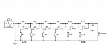
The main thing is the resistor network:
I attached a picture about a similar, but NOT R-2R network which has better sonic performance and it contains equal relays and resistors. (significant less signal loss)
2#
I guess the most of the people using less than 4 sources.
Maybe 3 input and 2 switchable output would be nice (personally I would use the 2nd output for my headphones amplifier and I don't need connect those parallel with the power amps.
3#
Dimmer or automatic down for backlight would be nice - in simple case with the "display" button on remote. (the compatibility with OLED/PLED display would be also nice)
4#
Optional I/V or buffer with a standard OPA would be nice if anyone would use it.
Please consider this advices for the future.
Thanks!
Others!
What do you think about my suggestions?
Hi bbp!
I would give some personal advices for v2:
1#
The main thing is the resistor network:
I attached a picture about a similar, but NOT R-2R network which has better sonic performance and it contains equal relays and resistors. (significant less signal loss)
2#
I guess the most of the people using less than 4 sources.
Maybe 3 input and 2 switchable output would be nice (personally I would use the 2nd output for my headphones amplifier and I don't need connect those parallel with the power amps.
3#
Dimmer or automatic down for backlight would be nice - in simple case with the "display" button on remote. (the compatibility with OLED/PLED display would be also nice)
4#
Optional I/V or buffer with a standard OPA would be nice if anyone would use it.
Please consider this advices for the future.
Thanks!
Others!
What do you think about my suggestions?
Attachments
Re: -> advices for v2
Thank you for your advice, cartman 🙂
1# 3# and 4# are very good
Maybe I will build a VOL kit like Marklevnsion No.32 later 😀
About 20 KITs left , go on and on
cartman said:Hi bbp!
I would give some personal advices for v2:
1#
The main thing is the resistor network:
I attached a picture about a similar, but NOT R-2R network which has better sonic performance and it contains equal relays and resistors. (significant less signal loss)
2#
I guess the most of the people using less than 4 sources.
Maybe 3 input and 2 switchable output would be nice (personally I would use the 2nd output for my headphones amplifier and I don't need connect those parallel with the power amps.
3#
Dimmer or automatic down for backlight would be nice - in simple case with the "display" button on remote. (the compatibility with OLED/PLED display would be also nice)
4#
Optional I/V or buffer with a standard OPA would be nice if anyone would use it.
Please consider this advices for the future.
Thanks!
Others!
What do you think about my suggestions?
Thank you for your advice, cartman 🙂
1# 3# and 4# are very good
Maybe I will build a VOL kit like Marklevnsion No.32 later 😀
About 20 KITs left , go on and on
To get back at the blown Cap, Up to now I have been a "penguin" but is it safe to hook the thing up or do we need to replace the cap first?
tHE pENGUIN
Hi Mr. Penguin ...öh I'm sorry hoka, and our master Mr. Lu 🙂
I don't know if my pictures bring anything to you Lu but anyway here they are.
For the penguin ... sorry hoka , you can dismantle the display and look at the cap mentioned. Is it turned the right way around? (look at Lu's picture above)
Then there shouldn't be any problem. But you never know....
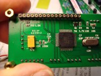
This is the original display after cap change
Hi Mr. Penguin ...öh I'm sorry hoka, and our master Mr. Lu 🙂
I don't know if my pictures bring anything to you Lu but anyway here they are.
For the penguin ... sorry hoka
, you can dismantle the display and look at the cap mentioned. Is it turned the right way around? (look at Lu's picture above)Then there shouldn't be any problem. But you never know....
This is the original display after cap change
Attachments

next picture
Real entertainment
In my pictures you can see that I have used quite a larger SMD cap (clumsy) at only 33uF. It's rated at 16 Volt though. I don't know Lu's choise of capacitor from the beginning. I had to scrape the card somewhat for fitting this one.
Real entertainment
In my pictures you can see that I have used quite a larger SMD cap (clumsy) at only 33uF. It's rated at 16 Volt though. I don't know Lu's choise of capacitor from the beginning. I had to scrape the card somewhat for fitting this one.
Attachments
Another display
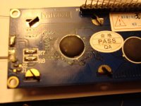
This is another picture of the display not connected. I have cleaned it from the soot.
As a very addicted DIY man I have a lot of componenets laying around.... and I have bought them all ... 😀 So I have tested with yet another display to no avail...
As everyone can see, the CPU is dead for me . I hope that this cap wont be any trouble for other diy people. But as I said above, check polarity of yours. Maybe you are like me, .... a Mr. Murphy man 😉


Anyway, the kit is very good  😀 😎
😀 😎
This is another picture of the display not connected. I have cleaned it from the soot.
As a very addicted DIY man I have a lot of componenets laying around.... and I have bought them all ...
😀 So I have tested with yet another display to no avail...As everyone can see, the CPU is dead for me . I hope that this cap wont be any trouble for other diy people. But as I said above, check polarity of yours. Maybe you are like me, .... a Mr. Murphy man 😉
Anyway, the kit is very good
😀 😎Attachments
Re: Another display
Hi Radioman62, I will send a new controller board with new LCD to you ^_^
Sorry to have this trouble happen to you, have a nice time🙂
regards
Lu
Radioman62 said:This is another picture of the display not connected. I have cleaned it from the soot.
As a very addicted DIY man I have a lot of componenets laying around.... and I have bought them all ...
As everyone can see, the CPU is dead for me . I hope that this cap wont be any trouble for other diy people. But as I said above, check polarity of yours. Maybe you are like me, .... a Mr. Murphy man 😉
Anyway, the kit is very good
Hi Radioman62, I will send a new controller board with new LCD to you ^_^
Sorry to have this trouble happen to you, have a nice time🙂
regards
Lu
Hello Cartman,
That looks like the same resistor network as discussed over here:
http://www.diyaudio.com/forums/showthread.php?s=&threadid=21198&highlight=
Regards,
Danny
That looks like the same resistor network as discussed over here:
http://www.diyaudio.com/forums/showthread.php?s=&threadid=21198&highlight=
Regards,
Danny
- Status
- Not open for further replies.