justblair said:Got mine yesterday, All seems good, got it powered up
Nice display, love the clicky sounds of the relays.
I haven't connected it to anything yet to try it, I wanted to check that this cable was right before I did.

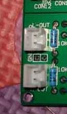
Its the one that connects the controller to the relay board. Is the twist meant to be in the cables, 4 and 5 (counting from the top of the picture) are swapped. Can either someone who has the kit, or Lu himself tell me if this is right?
Blair
Hi Justblair, the twisted cable is wrong. I am sorry aobut this mistake happened in your kit. You may correct it 🙂 🙂
bbp said:
Hi Justblair, the twisted cable is wrong. I am sorry aobut this mistake happened in your kit. You may correct it 🙂 🙂
Np, Its a very minor problem and a very easy fix. The kit is great, interested to hear if anyone has theirs up and running in an amplifier yet? It will be a week or two before I get mine set up.
looking forward to seeing whom get the kit to share their works.the kit should be better than the normal potentiometer,for instance, the balance and the separability.anyway,it's looks like a mini preamp without gain.
Can anyone point me at a Farnell or Radiospares reference for the connectors?
I am not sure how I am going to crimp those things - can ribbon be bought already connected to the headers?
I am wanting to add cables to the analog I/O - also the relay board +5v/GND
TIA
Cliff
I am not sure how I am going to crimp those things - can ribbon be bought already connected to the headers?
I am wanting to add cables to the analog I/O - also the relay board +5v/GND
TIA
Cliff
luzhu said:...it's looks like a mini preamp without gain.
ergo passive 🙂
bbp!
Is the gain able to reach the 100% (1x) gain with max attenuation? (on max.volume)
(or it has some loss)
😕
cartman said:
ergo passive 🙂
bbp!
Is the gain able to reach the 100% (1x) gain with max attenuation? (on max.volume)
(or it has some loss)
😕
Radioman62 said:I think it does
But if we only have the schematic ...
Hi Cartman and Radioman62,
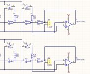
The VOL do have singal amplitude loss, because it's R-2R type circuit.
Here I add the SCH , you can find the output resistors R13 in LEFT channel and R20 in RIGHT channel, the amplitude is less when you short them with jumper or lower value resistors 🙂
The whole SCH seems to large to upload, I will add the whole SCH to the newer version user manual V1.2
regards
Lu
Attachments

cartman said:
ergo passive 🙂
bbp!
Is the gain able to reach the 100% (1x) gain with max attenuation? (on max.volume)
(or it has some loss)
😕
Hi Clifft,
It is not possible to reach 100% amplitude with max attenuation, the original output impedance is 10K+10k(R13 or R20). So if your amplifier has a input impedance 100K, you will get 100K/100K+10K+10K=83% signal amplitude max.

Short the two resistors , you will get less amplitude loss
100K/100K+10K=90.9% 😀
regards
Attachments
cliffforrest said:Can anyone point me at a Farnell or Radiospares reference for the connectors?
I am not sure how I am going to crimp those things - can ribbon be bought already connected to the headers?
I am wanting to add cables to the analog I/O - also the relay board +5v/GND
TIA
Cliff
Hi Cliff, do you mean you have no chassis,no RCA for audio I/O ?
bbp said:
Hi Cliff, do you mean you have no chassis,no RCA for audio I/O ?
No! Just the same connectors as you supplied in the kit.
I have soldered the supplied male headers into the pcb. I now need matching female connectors to connect them to the chassis RCAs.
I can't seem to find the exact Molex part on the Farnell site - there are hundreds of different pcb-connector variations.
bbp said:
...So if your amplifier has a input impedance 100K, you will get 100K/100K+10K+10K=83% signal amplitude max.
Short the two resistors , you will get less amplitude loss
100K/100K+10K=90.9% 😀
regards
But my amp input imp. is 10K only, so with your figure: 10K / (10K+10K+10K) = 33.3% 🙁
with jumper instead of last 10K resistor: 10K / (10K+10K+0) = 50% 🙁
Half of the signal will loss...
Maybe I have to use 1K and 2K resistors as R & 2R, because my CDP's output imp. is 50 ohm only (on the RCA and XLR output as well) based on the spec...
What do you think bbp?
What do you think bbp?
cartman said:Maybe I have to use 1K and 2K resistors as R & 2R, because my CDP's output imp. is 50 ohm only (on the RCA and XLR output as well) based on the spec...
What do you think bbp?
It doesn't work like that! 🙂
A low output impedance into a high input impedance is ideal - with a ratio of at least 10 and preferrably >100. Then there is no appreciable loading of the output.
Source output impedance does NOT have to match Pre input impedance.
Cliff
cliffforrest said:
It doesn't work like that! 🙂
A low output impedance into a high input impedance is ideal - with a ratio of at least 10 and preferrably >100. Then there is no appreciable loading of the output.
Source output impedance does NOT have to match Pre input impedance.
Cliff
Hi Cliff,
as you said, so I need at least 500 ohm input impedance (or ~5K) on Pre input.

As I know, the impedance matching is preferable...
What do you think about Jos's similar project? 2^6 (64step) attenuator (but that isn't R-2R)
Jos's project link
cliffforrest said:
No! Just the same connectors as you supplied in the kit.
I have soldered the supplied male headers into the pcb. I now need matching female connectors to connect them to the chassis RCAs.
I can't seem to find the exact Molex part on the Farnell site - there are hundreds of different pcb-connector variations.
Can you help, Lu?
Standard Molex KK parts have pins which are too big (1mm) to fit into your PCB 🙁
I need crimped cable connectors to fit to your supplied headers, or a pair of headers/females which will fit your PCB.
Your connectors have no markings. What is the source?
I will NOT connect wires direct to the PCB!
cartman said:Maybe I have to use 1K and 2K resistors as R & 2R, because my CDP's output imp. is 50 ohm only (on the RCA and XLR output as well) based on the spec...
What do you think bbp?
Hi cartman, for output impedance, the lower the best.
Maybe you need to add a I/V op after the attenuator, then you will have a output impedance below 50 ohm,
Attachments
etcetera said:Are these still available? If so I'd like to order one.
Eric
Hi etcetera, kits are in stock
cliffforrest said:
Can you help, Lu?
Standard Molex KK parts have pins which are too big (1mm) to fit into your PCB 🙁
I need crimped cable connectors to fit to your supplied headers, or a pair of headers/females which will fit your PCB.
Your connectors have no markings. What is the source?
I will NOT connect wires direct to the PCB!
Hi Cliff,
Don't worry, I will send 4 * 4P connecting cable to you later , for free 🙂
regards
Lu
- Status
- Not open for further replies.